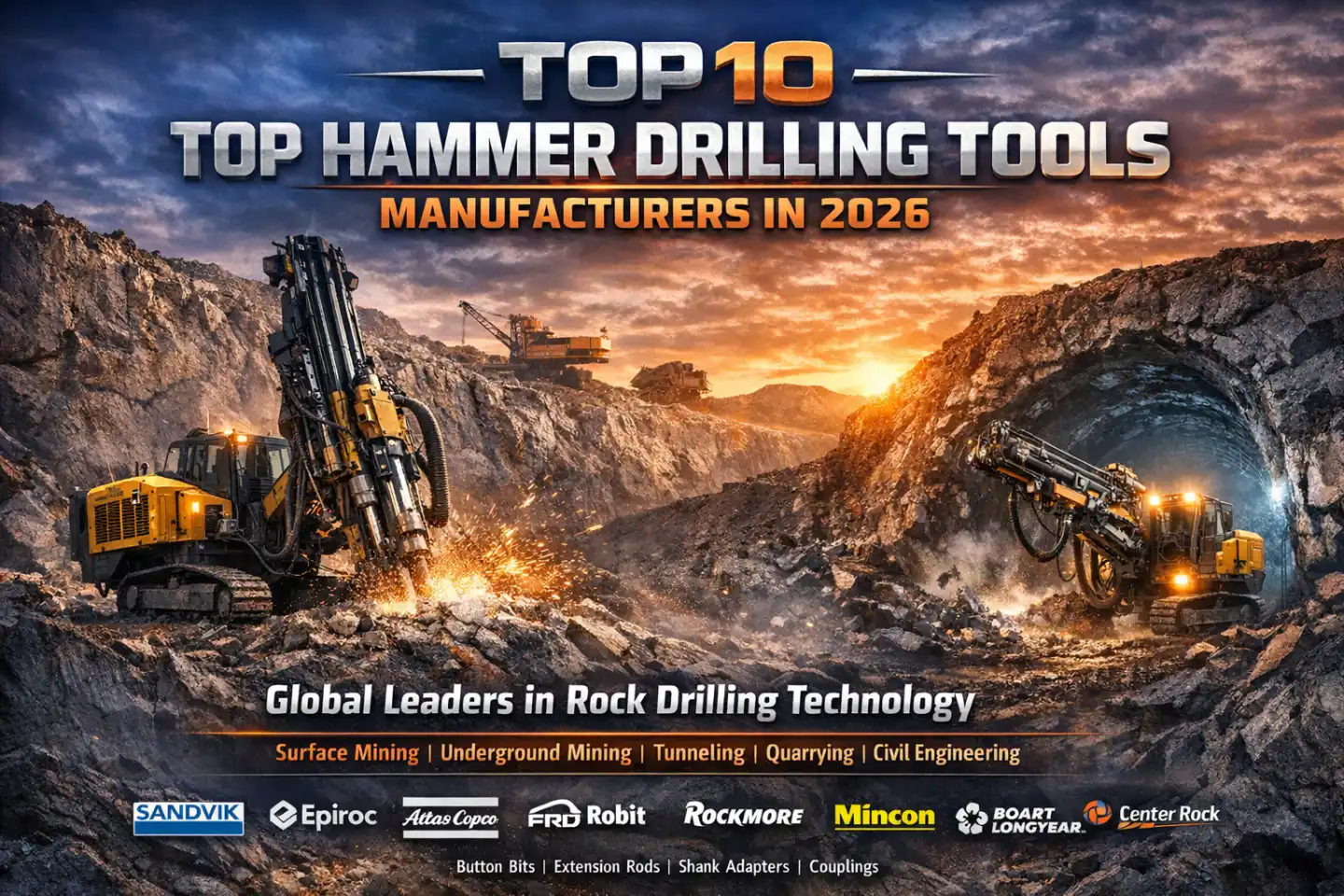
Table of Contents
Introduction
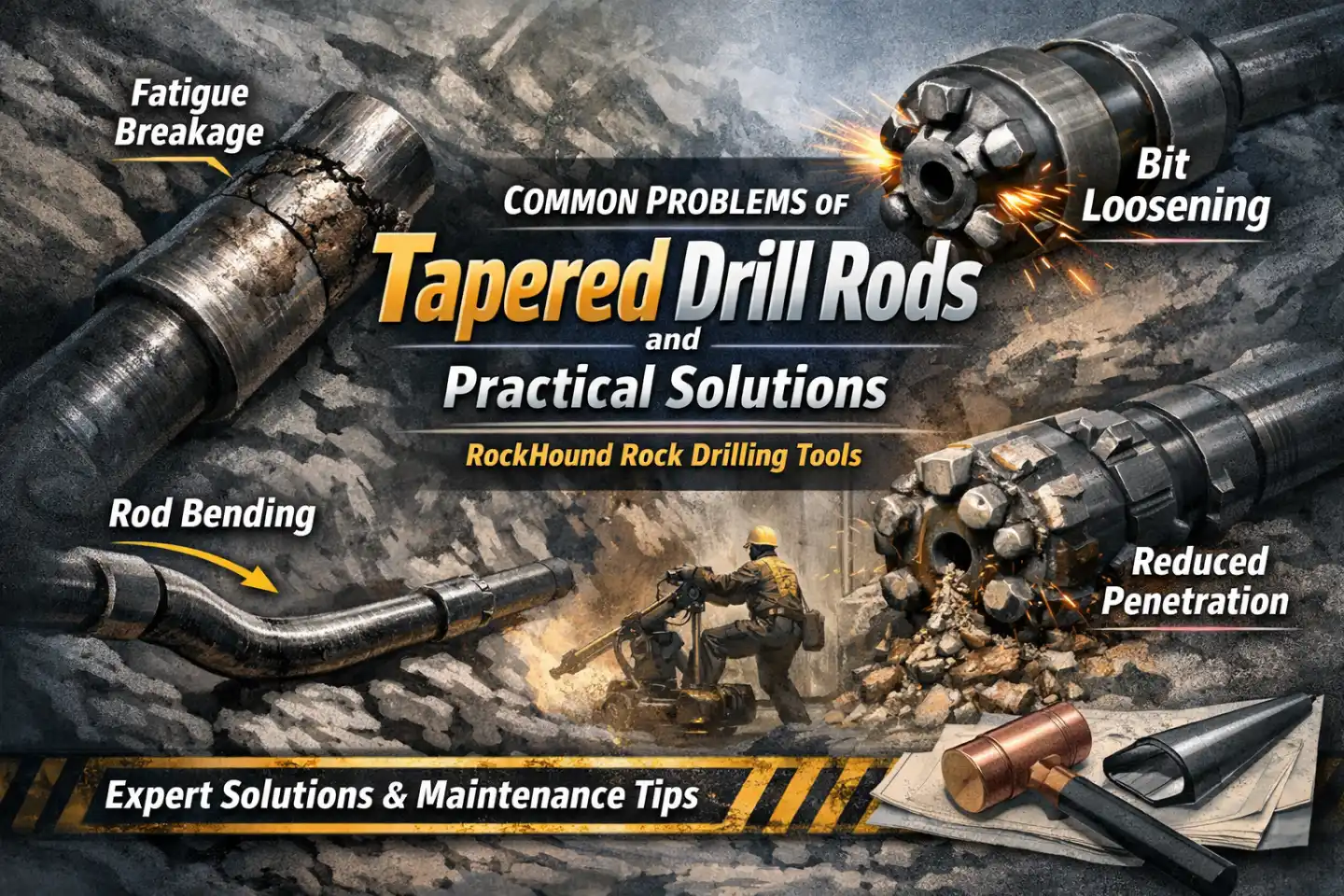
In any percussive or rotary-percussive drilling system — whether applied to underground mining, quarrying, tunneling, or construction anchoring — the threaded rock drilling rod is the highest-wear consumable in the drill string. It transmits impact energy and rotational torque from the rock drill to the bit while simultaneously serving as a conduit for flushing media. Because it operates under continuous cyclic loading in abrasive, high-humidity environments, its manufacturing quality directly controls rig uptime and cost per meter drilled (CPM).
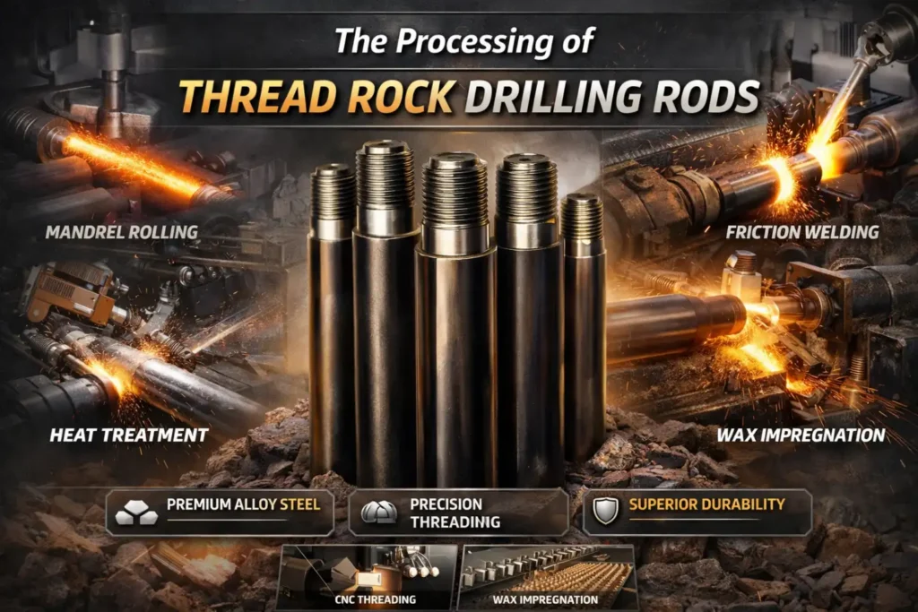
This guide walks through the complete 10-step production process used at RockHound — from alloy billet selection to final packaging — explaining the metallurgical rationale behind each stage and the performance outcomes operators can expect in the field.
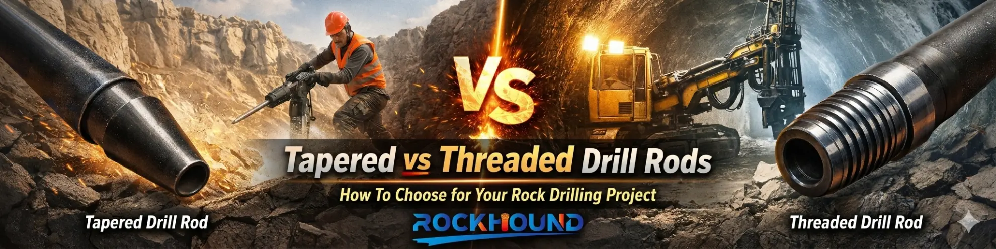
Related reading: Not sure which rod type suits your application? Start with our overview: Rock Drill Rods: Types, How They Work, How to Choose & Maintenance
Step 1 — Raw Material & Billet Preparation: Mandrel Rolling vs. Hot Piercing
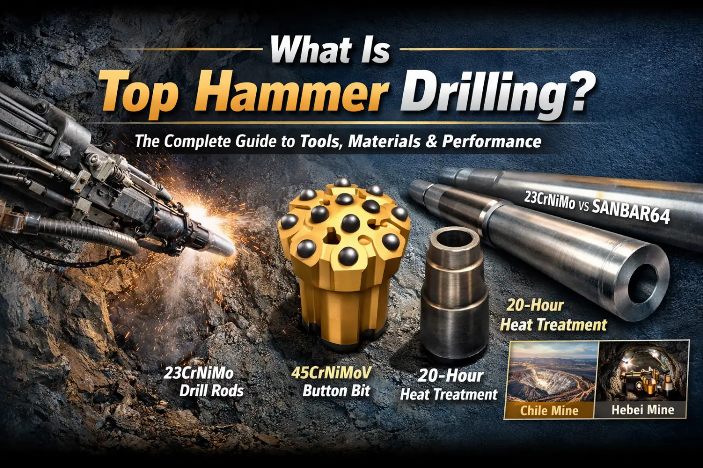
Alloy Steel Selection: ZK22CrNi3Mo
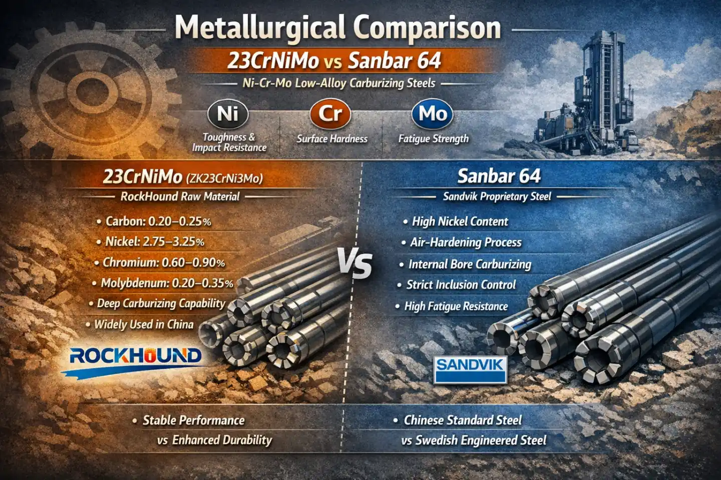
All RockHound threaded drill rods are produced from ZK22CrNi3Mo alloy steel (as know as 23CrNiMo) — a premium low-alloy, high-strength structural steel selected for its exceptional combination of fatigue strength, deep hardenability, and impact toughness. The nominal chemical composition targets 0.22% C, 1.34% Cr, 3.05% Ni, and 0.25% Mo — a balance that produces a fine-grained martensitic core after heat treatment while supporting a deep, adherent carburized case on the surface.
Mandrel Rolling (Center-Core Extraction)
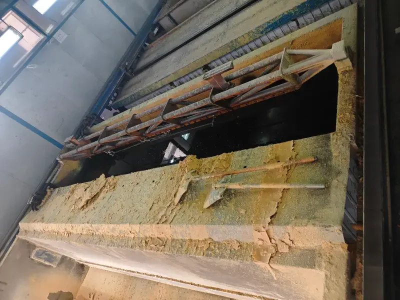
- The flushing bore — the longitudinal hole through which water or compressed air is circulated to cool the bit and evacuate drill cuttings — is formed by mandrel rolling rather than conventional hot piercing. The process begins with a 180–200 mm square billet or a ≤160 mm round billet. Central drilling removes core material and potential segregation defects; a high-alloy mandrel is then inserted; and the assembly is passed through multiple rolling passes to achieve the final hollow bar dimensions.

Technical advantages of mandrel rolling over hot piercing:

- Mirror-smooth bore walls: Eliminates the tool-mark striations left by piercing plugs. Stress concentration at internal surface defects is the primary initiation site for fatigue cracks — removing these defects directly extends rod service life.
- Precision ovality: The slightly elliptical bore geometry is intentionally engineered to optimize stress distribution under high-frequency axial and torsional loading during top-hammer operation.
- Superior microstructural density: Mandrel-rolled tube achieves a material yield of ≥80% with a compacted grain structure throughout the wall thickness — versus the looser grain morphology common to hot-pierced tube.
Hot Piercing: Why We Don't Use It
The conventional hot piercing process heats the entire billet to a plastic state and forms the bore using a piercing plug. While it produces a perfectly circular bore, it cannot prevent tool-mark striations and micro-scratches on the bore wall. These internal surface defects create stress concentration points that directly seed fatigue crack initiation — the leading cause of premature rod fracture in the field.
Comparative overview
| Attribute | Mandrel Rolling | Conventional Hot Piercing |
|---|---|---|
| Bore surface finish | Smooth — minimal Ra | Prone to tool-mark striations |
| Internal stress risers | Absent | Micro-cracks possible |
| Bore geometry | Precision elliptical | Circular, tolerances wider |
| Material yield | ≥80% | Typically lower |
| Fatigue crack initiation risk | Significantly reduced | Higher — inner wall defects |
Step 2 — Precision Length Cutting & Chemical Certification
Once the hollow bar is received from the rolling mill, it is cut to ordered rod length on dedicated cold-saw or abrasive cut-off equipment. Length tolerances are held within the applicable execution standard (e.g., Q/JSGB6-2011 for drifting rods), ensuring consistent drill-string assembly without shim adjustments in the field.
Every production batch is accompanied by a mill certificate with spectrometric chemical analysis. Representative measured values for a qualified H25×2000-R25 drifter rod batch:
| Element | C | Si | Mn | Cr | Ni | Mo | Cu |
|---|---|---|---|---|---|---|---|
| Measured (%) | 0.22 | 0.30 | 0.73 | 1.34 | 3.05 | 0.25 | 0.04 |
| Trace Element | S | P | Ti | As | Sn | Al | Status |
|---|---|---|---|---|---|---|---|
| Measured (%) | 0.014 | 0.010 | 0.003 | 0.005 | 0.004 | 0.026 | PASS |
The elevated Ni (3.05%) and Mo (0.25%) levels are significant: nickel enhances the case-to-core toughness transition and subzero impact resistance, while molybdenum refines austenite grain size and suppresses temper embrittlement — both critical for underground drill rod applications where ambient temperatures fluctuate widely.
Explore:Rock Drill Rod Material Comparison:23CrNiMo vs Sanbar64
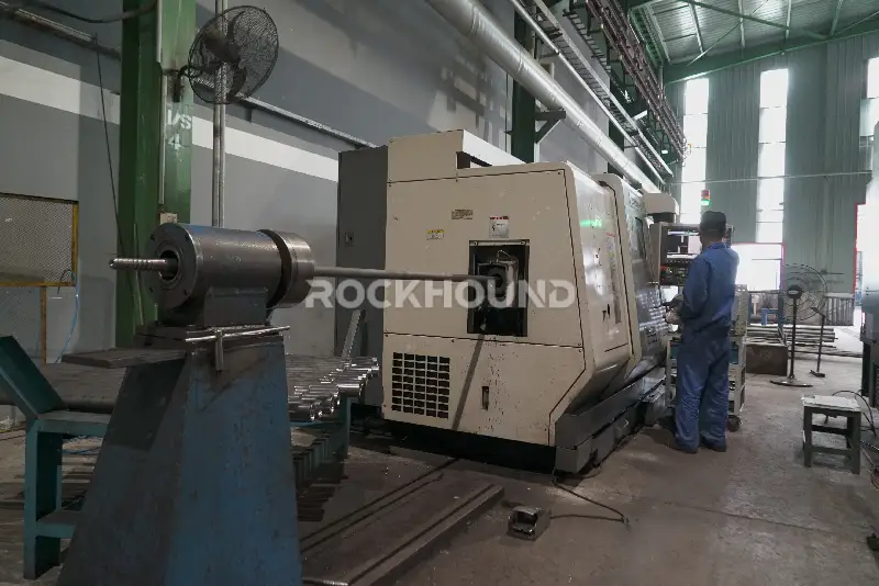
Step 3 — Rotary Straightening (Pre-Machining)
Hollow bar received from the rolling mill carries residual bending stress from the rolling process itself. Left uncorrected, even slight camber (bow) causes dynamic balance errors during rotation, accelerating wear at the drill chuck and rod coupler and reducing the accuracy of the percussive blow transmitted to the bit.
All bar stock is therefore passed through a rotary straightening machine prior to any threading or forming operations. The objective is two-fold: to eliminate macro-level bow and to relieve residual bending stress — ensuring concentricity of the flushing bore relative to the OD, a prerequisite for balanced high-speed rotation in top-hammer and drifter applications.
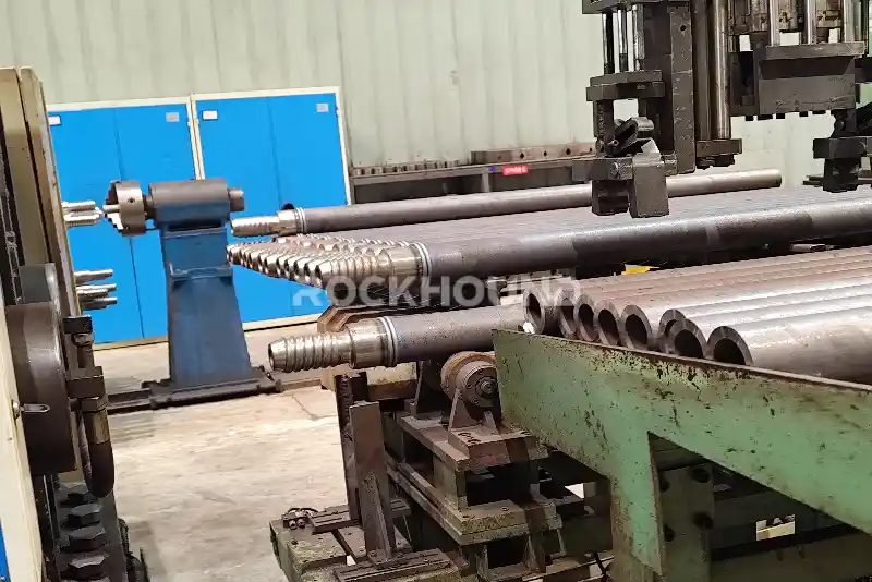
Step 4 — Thread Forming: Friction Welding & Forging Upsetting
The threaded joint is the single most mechanically demanding location on a drill rod. It must transmit both axial impact loads and rotational torque while remaining resistant to thread stripping, fatigue fracture, and galling. Two alternative processes are used depending on rod diameter and thread geometry:
Friction Welding (Rotary Inertia Welding)
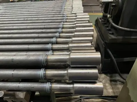
For standard-diameter rods up to approximately 52 mm, a pre-machined alloy steel joint is joined to the rod body by continuous-drive friction welding. The joint and rod body are brought into contact under controlled axial force while one component rotates at high speed; frictional heat plasticizes the interface; rotation stops and an upset (forging) force consolidates the weld zone. The resulting bond achieves weld-zone strength equal to or exceeding that of the parent material, with no filler metal and a narrow heat-affected zone.

Post-weld flash (inner and outer upset beads) is fully removed by CNC turning to eliminate any geometric stress concentration at the weld plane.
Process control parameters: upsetting pressure, spindle RPM, and friction time are monitored and logged for each weld cycle to ensure interface temperature uniformity and reproducible metallurgical bonding.
Note: Flash removal is not required for guide (pilot) drill rods or rods larger than 52 mm, as the larger bore diameter provides adequate flushing-media flow cross-section without modification.
Forging Upsetting (Hot Die Forging)
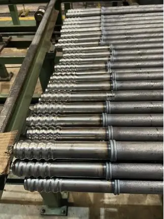
For large-diameter threaded ends where the thread OD exceeds the rod body OD — or where internal thread machining is required for coupled-rod systems — the rod end is locally upset by hot die forging on a 250-ton hydraulic forging press after induction heating to forging temperature. The enlarged, work-hardened end forging is then machined to final thread form (R-thread, T-thread, or ballistic profile) by CNC threading operations.
This process produces thread roots with a higher material density and compressive residual stress than machined-from-solid threads — critical for fatigue performance at the thread root, which is statistically the most common fracture initiation site in field-failed drill rods.
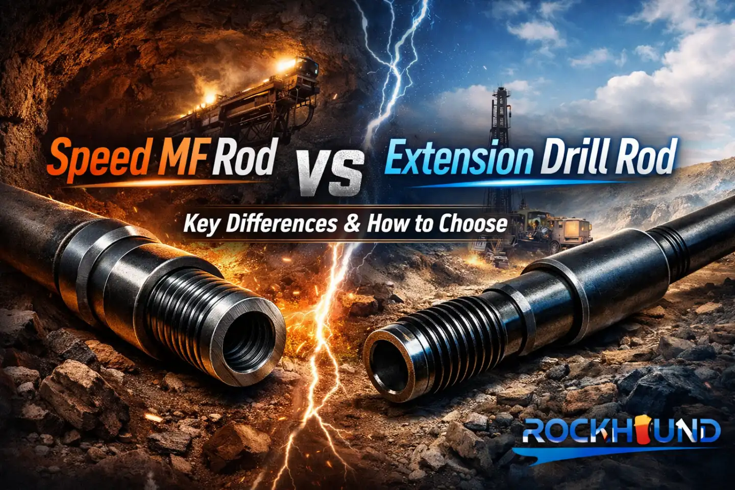
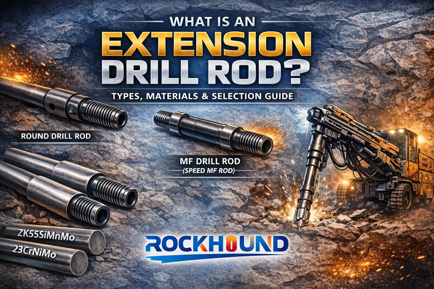
Related reading: Wondering how coupled extension rods differ from integral-steel rods in joint design? See: What Is an Extension Drill Rod? Types, Materials & Selection Guide
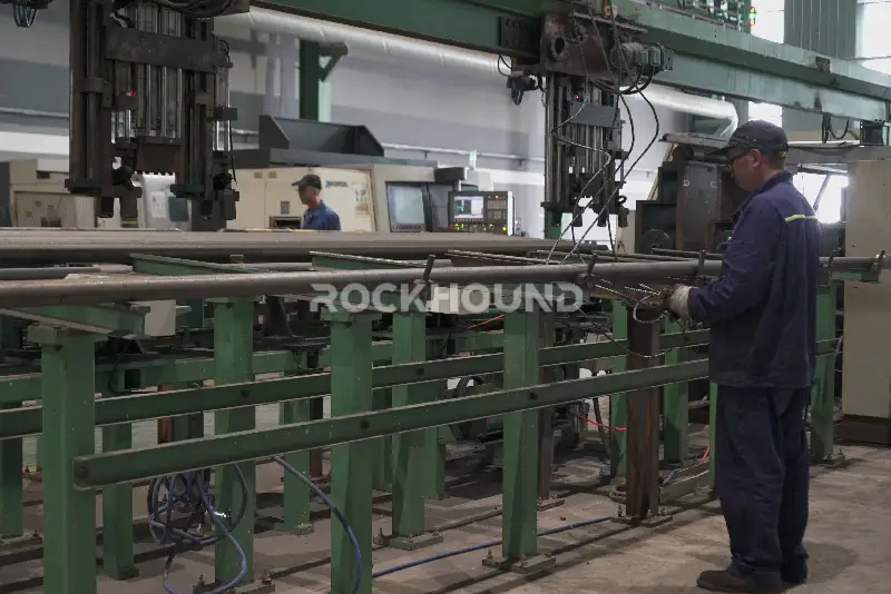
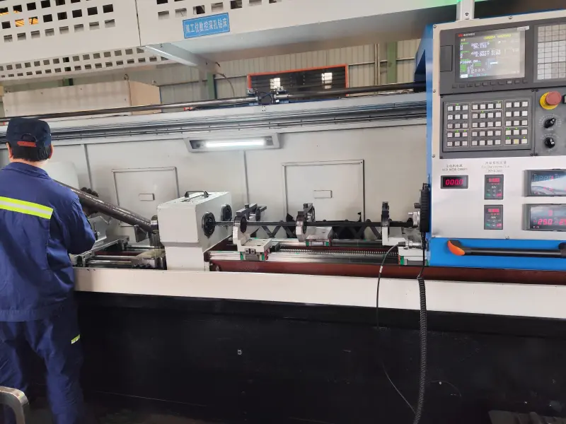
Step 5 — CNC Turning & Flash Removal
Following friction welding or forging upsetting, the rod undergoes CNC turning of the body OD and the weld/forge transition zones:
- For rods ≤52 mm diameter: All internal and external weld flash must be fully removed. Any remaining protrusion inside the bore constitutes a flow restriction that increases flushing pressure drop and — more critically — creates a stress concentration feature that can nucleate internal fatigue cracks under cyclic flushing-water pressure.
- For rods ≥52 mm diameter: The larger bore provides adequate flow cross-section without flash removal, simplifying the machining sequence.
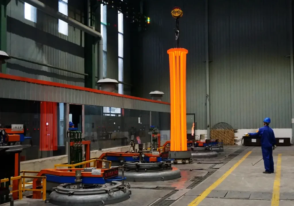
Step 6 — Heat Treatment: The 20-Hour Deep Carburization Cycle
Heat treatment is the most critical determinant of drill rod service life. To perform reliably under the combined demands of high-frequency percussion (35–70 Hz in top-hammer systems), rotational torque, and abrasive rock contact, a drill rod must exhibit a “hard case / tough core” microstructure — a high-hardness, wear-resistant carburized surface layer over a ductile, fatigue-resistant core.
Equipment & Batch Homogeneity
RockHound operates eight pit-type carburizing furnaces, five of which have a working length of 7 m and can accommodate rods up to 6.5 m. Strict batch homogeneity is enforced: all rods in a single furnace load must be of identical specification. Mixed loading is prohibited — variations in rod OD alter the surface-area-to-mass ratio and distort the local carbon-potential gradient, producing inconsistent case depth across a batch and compromising product reliability.
The 20-Hour Cycle vs. The Industry Standard
The industry standard carburization cycle for rock drill rods is 8–13 hours. RockHound’s process runs for 20 hours in total, covering gas carburizing, direct quenching, low-temperature tempering, and controlled cooling to ambient. The extended cycle is not simply a longer version of the same process — it enables fundamentally different metallurgical outcomes:
| Technical Parameter | Standard Industry Process (8–13 h) | RockHound 20-Hour Process | Field Impact |
|---|---|---|---|
| Effective case depth (ECD) | 1.0–1.5 mm | 2.0–3.0+ mm | Doubled wear resistance in high-quartz and ultra-hard formations |
| Carbon gradient profile | Steep — prone to case spalling | Gentle / smooth | Eliminates brittle case delamination; no abrupt stress riser at case-core interface |
| Core microstructure | Moderate toughness; incomplete grain refinement | Refined grain structure; high strength + toughness | Superior fatigue life under cyclic high-frequency loading |
| Internal bore fatigue resistance | Susceptible to micro-crack initiation | Optimized compressive stress distribution | Reduces internal crack propagation in high-pressure wet drilling |
| Expected service life vs. baseline | 100% (baseline) | 140–160% | 40–60% lower CPM; higher rig uptime |
Explore More:20 Hour Heat Treatment In Rock Drilling Tools
The gentle carbon concentration gradient achieved by the extended cycle deserves particular emphasis. In a steep-gradient carburized rod, the abrupt transition from high-carbon martensite (hard, brittle) to low-carbon martensite (tough) creates a stress discontinuity that acts as a delamination plane under cyclic loading. The 20-hour cycle allows carbon to diffuse more deeply and uniformly, producing a smooth graded interface with no discrete brittle layer — directly addressing the spalling failure mode observed in short-cycle treated rods.
The bottom line: we invest more in electricity, gas, and furnace time so that you spend less on replacements and unplanned downtime.
Step 7 — Fully Automatic Straightening (Post-Hardening)
Quenching from carburizing temperature invariably introduces thermal distortion. Even with carefully controlled cooling rates, rods longer than approximately 1 m will experience some bow. Post-hardening straightening is therefore mandatory before any finishing operations.
RockHound currently operates an automatic straightening machine capable of calibrating rods up to 2 m in length. To support longer rod production — particularly 3.7 m, 4.8 m, and 6.1 m mining rods — Shougang Guiyang Special Steel, RockHound’s primary supply chain partner, has committed to installing a 6 m automated straightening machine in 2026, eliminating the manual press-straightening step currently applied to longer rods.
Step 8 — Shot Peening & Surface Finishing
After straightening, the rod body is processed through a shot peening machine using controlled steel shot media. Shot peening serves two distinct functions:
- Scale removal: Oxidation products (heat-treat scale) formed during carburizing are mechanically stripped, providing a clean, receptive surface for subsequent anti-corrosion treatment.
- Compressive residual stress induction: The kinetic impact of shot media cold-works the outer 0.1–0.3 mm of the surface layer, converting surface tensile residual stresses (which promote fatigue crack opening) into beneficial compressive residual stresses (which retard crack initiation). This is a recognized surface enhancement technique referenced in ISO and ASME fatigue design standards.
The rod shank and mid-body sections then undergo cylindrical grinding and centerless finishing to achieve the dimensional tolerances and surface roughness (Ra) required for proper chuck fit and coupling engagement.
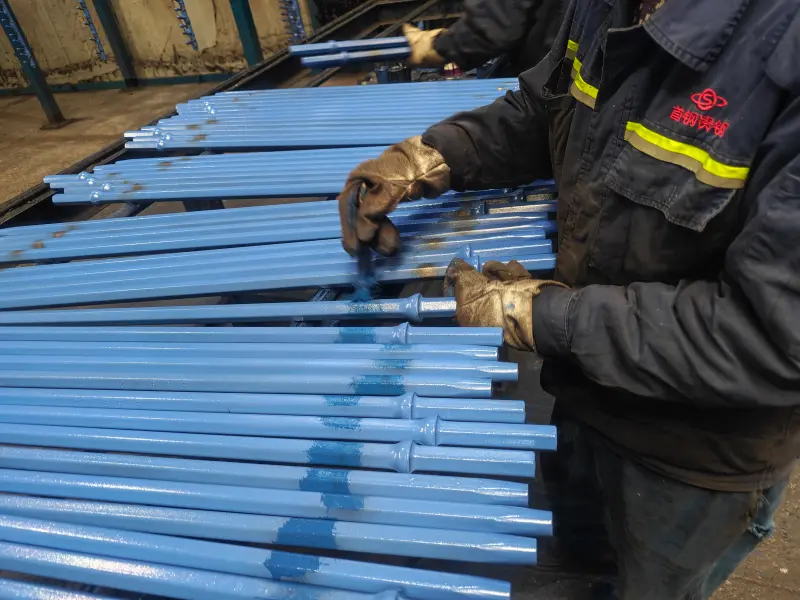
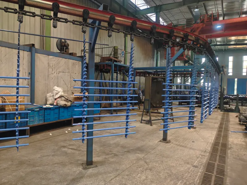
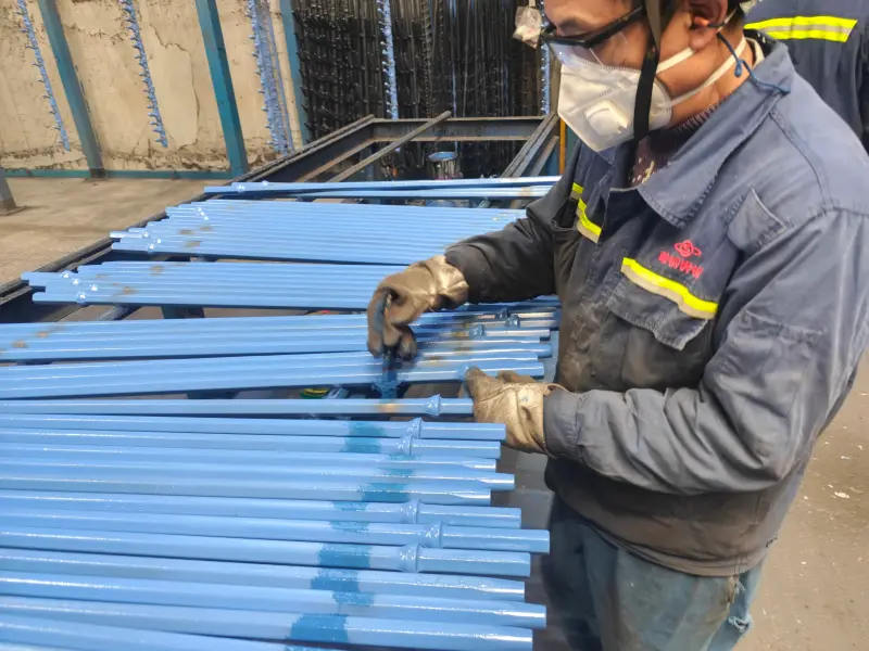
Step 9 — Anti-Corrosion Treatment: Wax Impregnation, Phosphating & Painting
Rock drill rods are routinely stored and transported for months before deployment in wet underground environments. Corrosion of the flushing bore is a particular concern: rust pitting inside the bore creates stress concentration features analogous to manufacturing defects, prematurely degrading fatigue life before a single hole is drilled. RockHound applies tiered corrosion protection depending on rod length and customer specification:
| Treatment | Application Scope | Protection Mechanism |
|---|---|---|
| Full-length wax impregnation | Rods ≤4.5 m — complete submersion, ID and OD | Wax penetrates and seals the bore; superior inner bore protection vs. painting; waterproof barrier against aggressive mine-water chemistry |
| Oil impregnation | Rods up to 6 m — shank and threaded tip zones | Rust-preventive oil film on thread form and shank taper; prevents galling and corrosive thread wear during storage |
| Phosphating | Optional — per customer specification | Conversion coating providing a porous base layer for improved paint adhesion and mild chemical barrier against oxidation |
| Electrostatic spray painting | Outer surface — standard black anti-rust paint | Visual quality; secondary corrosion barrier; color-coded batch identification |
Why wax impregnation outperforms painting for bore protection: Spray paint cannot coat the internal bore of a drill rod. Wax impregnation submerges the entire rod — including the flushing bore — ensuring that the most fatigue-critical surface is protected from the moment the rod leaves the facility until it enters service.
- Phosphating: Improves chemical protection (optional).
- Electrostatic spraying: External surface treatment, commonly using black anti-rust paint, emphasizing visual quality.
- Overall wax impregnation (≤4.5m): Impregnation of the entire shaft, both inside and out. Advantages: Extremely strong corrosion resistance to the inner bore; rust prevention is superior to painting.
- Oil impregnation (≤6m): Primarily for rust protection of the shank and tip (threaded area).
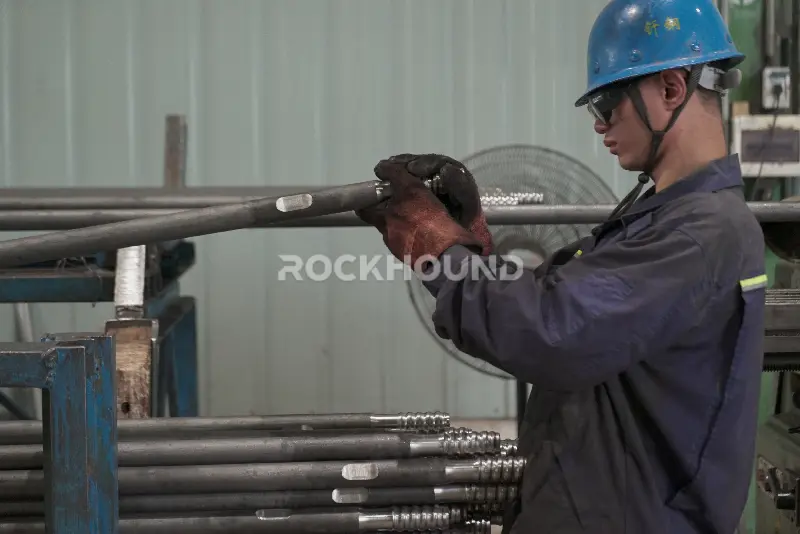
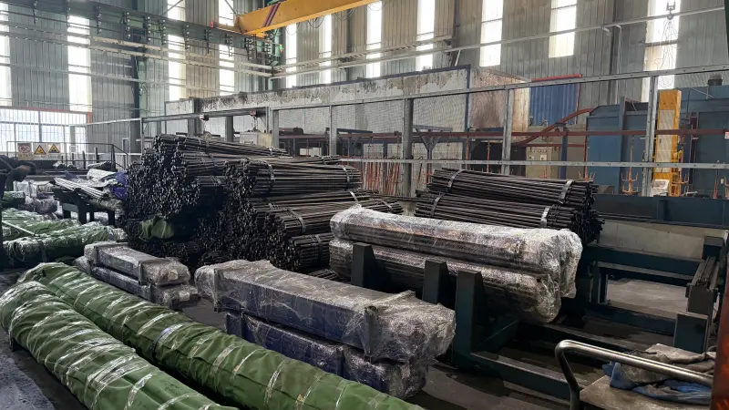
Step 10 — Final Inspection, Marking & Packaging
Before release, each rod passes a final quality gate: dimensional inspection, visual inspection for surface defects, and batch record reconciliation against the mill certificate and heat treatment process logs. Non-conforming rods are quarantined and disposition-reviewed.
Identification Marking
Rods are marked with specification, material grade, and production batch via laser marking or steel-stamp die marking on the shank flat or hex body (standard marking field: 100×100 mm). Full traceability back to the original mill heat and furnace cycle is maintained — a key requirement for operators working in regulated mining environments where material certification is mandatory. Note: marking is available as a value-added service; specifications and cost are confirmed at order placement.
Packaging Options
- Steel-banded bundle: Standard bulk packaging for most export shipments, bundled with moisture-barrier wrap.
- Custom wooden crate (framed packaging): Available on request for premium-grade orders or projects requiring damage-free site delivery. Lead time and cost are confirmed with the logistics team at order placement.
Why Manufacturing Process Determines Your Cost Per Meter
Rock drill rods fail in three characteristic modes: fatigue fracture at the thread root or weld zone, abrasive wear of the carburized surface, and internal bore cracking driven by flushing-pressure fatigue or corrosion-assisted crack growth. Every step in the manufacturing sequence above is specifically targeted at one or more of these failure modes:
- Mandrel rolling → eliminates bore-surface defects that seed internal fatigue cracks
- ZK22CrNi3Mo alloy → provides hardenability depth and impact toughness at the core
- Friction welding + forging upsetting → ensures the joint is never the weak link
- 20-hour deep carburization → doubles effective case depth and smooths the carbon gradient to prevent spalling
- Shot peening → converts surface tensile stress to compressive, raising the fatigue threshold
- Full-length wax impregnation → eliminates bore pitting that would otherwise act as a fatigue notch after deployment
The cumulative result is a rod that delivers 40–60% longer service life compared to industry-standard product — directly lowering CPM and reducing unplanned downtime.
Also in this series:
Specify the Right Rod for Your Formation
RockHound manufactures threaded drill rods for top-hammer, drifter, and extension-rod applications in diameters from 22 mm to 76 mm and lengths up to 6.1 m — including R-thread, T-thread, and ballistic-profile connections. All rods are supplied with full mill certificates and heat treatment process records.
Contact the RockHound technical team with your drill model, formation type, and required rod diameter to receive a specification recommendation and CPM comparison for your application.
FAQ
RockHound threaded rock drilling rods are manufactured from ZK22CrNi3Mo low-alloy, high-strength steel. This grade is selected for its combination of high fatigue strength, deep hardenability, and impact toughness — properties critical for withstanding the high-frequency percussive loading and abrasive rock contact in top-hammer and drifter drilling applications. The alloy contains 0.22% carbon, 1.34% chromium, 3.05% nickel, and 0.25% molybdenum, verified by spectrometric chemical analysis for every production batch.
Mandrel rolling (also known as center-core extraction rolling) is a tube-forming process where a high-alloy mandrel is inserted into a pre-drilled billet before rolling, producing a smooth, dense flushing bore. Compared to conventional hot piercing, mandrel rolling eliminates the tool-mark striations left inside the bore by piercing plugs. Those internal surface defects are the primary initiation sites for fatigue cracks in drill rods. Mandrel rolling achieves a mirror-smooth bore wall, a precision elliptical bore geometry that optimizes stress distribution under high-frequency percussion, and a material yield of over 80%.
RockHound drill rods undergo a 20-hour deep carburization heat treatment cycle, compared to the industry standard of 8 to 13 hours. The extended cycle achieves an effective case depth of 2.0–3.0+ mm (versus 1.0–1.5 mm for standard processes) and produces a gentle carbon concentration gradient from the hardened surface to the tough core. This smooth gradient prevents the brittle case spalling and sudden fracture common in short-cycle treated rods. The result is a 40–60% increase in service life and a significantly lower cost per meter drilled.
Both processes are used to form the threaded joint at the rod end, but they apply to different rod sizes. Friction welding (rotary inertia welding) is used for standard-diameter rods up to approximately 52 mm: a pre-machined alloy joint is bonded to the rod body under controlled axial force and rotational speed, achieving weld-zone strength equal to the parent material with no filler metal. Forging upsetting uses a 250-ton hydraulic forging press to locally enlarge the rod end at forging temperature, and is applied when the thread OD exceeds the rod body OD or when internal threads are required. Forging upsetting produces compressive residual stress at the thread root — the most common fatigue fracture initiation site in field-failed drill rods.
RockHound applies tiered corrosion protection based on rod length and application. Rods up to 4.5 m receive full-length wax impregnation — the entire rod, including the flushing bore, is submerged in a wax bath, providing superior inner bore protection compared to painting alone. Rods up to 6 m receive oil impregnation on the shank and threaded tip zones to prevent galling and corrosive thread wear during storage. Optional phosphating and electrostatic spray painting (black anti-rust paint) are available for additional surface protection and batch identification.
Cost per meter (CPM) is the total consumable and downtime cost divided by the total meters drilled, and it is the key performance metric for evaluating drill rod value. A cheaper rod with a shorter service life often results in a higher CPM than a premium rod, because frequent rod changes increase both consumable spend and non-productive rig time. RockHound's 20-hour carburization cycle, mandrel-rolled bore, and shot-peened surface collectively extend rod service life by 40–60% compared to industry-standard product, delivering a measurably lower CPM in hard rock formations such as granite and quartzite.
RockHound manufactures threaded rock drilling rods with standard percussive drill rod thread profiles including R-thread (round thread), T-thread (tapered thread), and ballistic-profile connections, covering rod diameters from 22 mm to 76 mm and lengths up to 6.1 m. All rods are supplied with full mill certificates and heat treatment process records. Custom thread forms and dimensions are available — contact the RockHound technical team with your drill model and formation details for a specification recommendation.