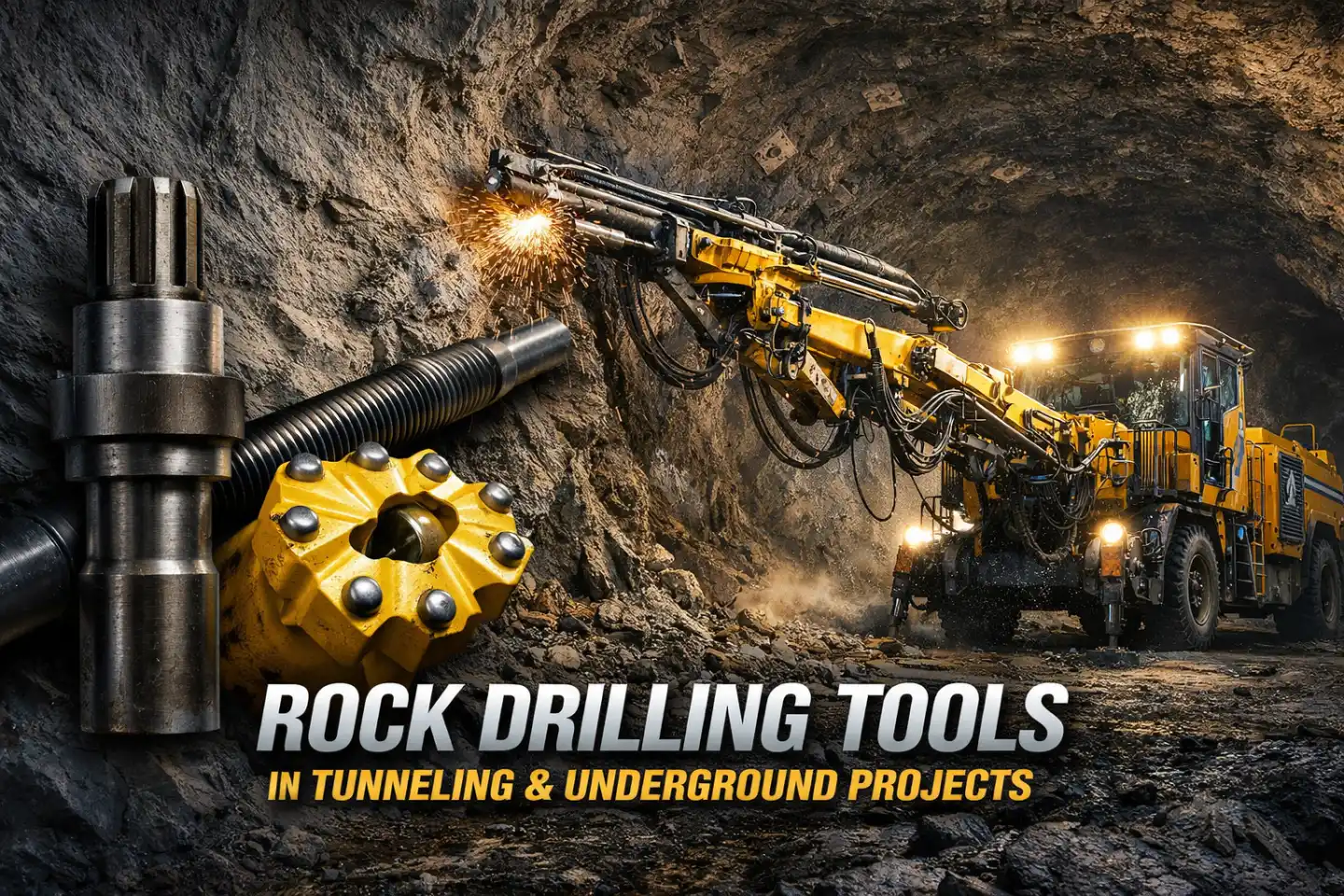
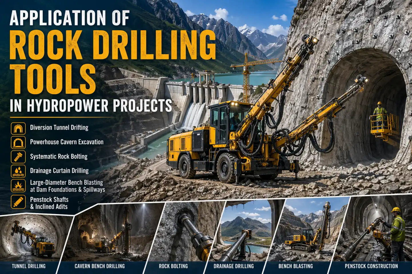
Hydropower construction is not a single job. It is a collection of different civil engineering challenges stacked on top of each other — diversion tunnels that need to redirect entire rivers, underground powerhouse caverns the size of sports arenas, dam abutments anchored into fractured valley walls, and penstock shafts that drop hundreds of meters through solid rock. Every one of these tasks depends on drilling, and the choice of rock drilling tools shapes how fast the work moves and how much of the budget survives.
Top hammer technology sits at the center of most of this work. Hydraulic jumbo-mounted tools handle face drilling in tunnels and drifts. Long-hole rigs run production blasting and rock reinforcement patterns in caverns. Specialized large-diameter tools cut bench rounds at dam foundations and spillways. Understanding which tool goes where — and why — is the starting point for any serious procurement decision on a hydropower project.
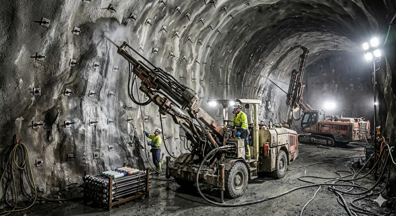
Diversion Tunnel Drifting
Before a dam goes up, the river has to go somewhere else. That job falls on the diversion tunnel — often the first major excavation on site and one of the most time-critical. A delay here pushes back everything downstream, so penetration rate matters from day one.
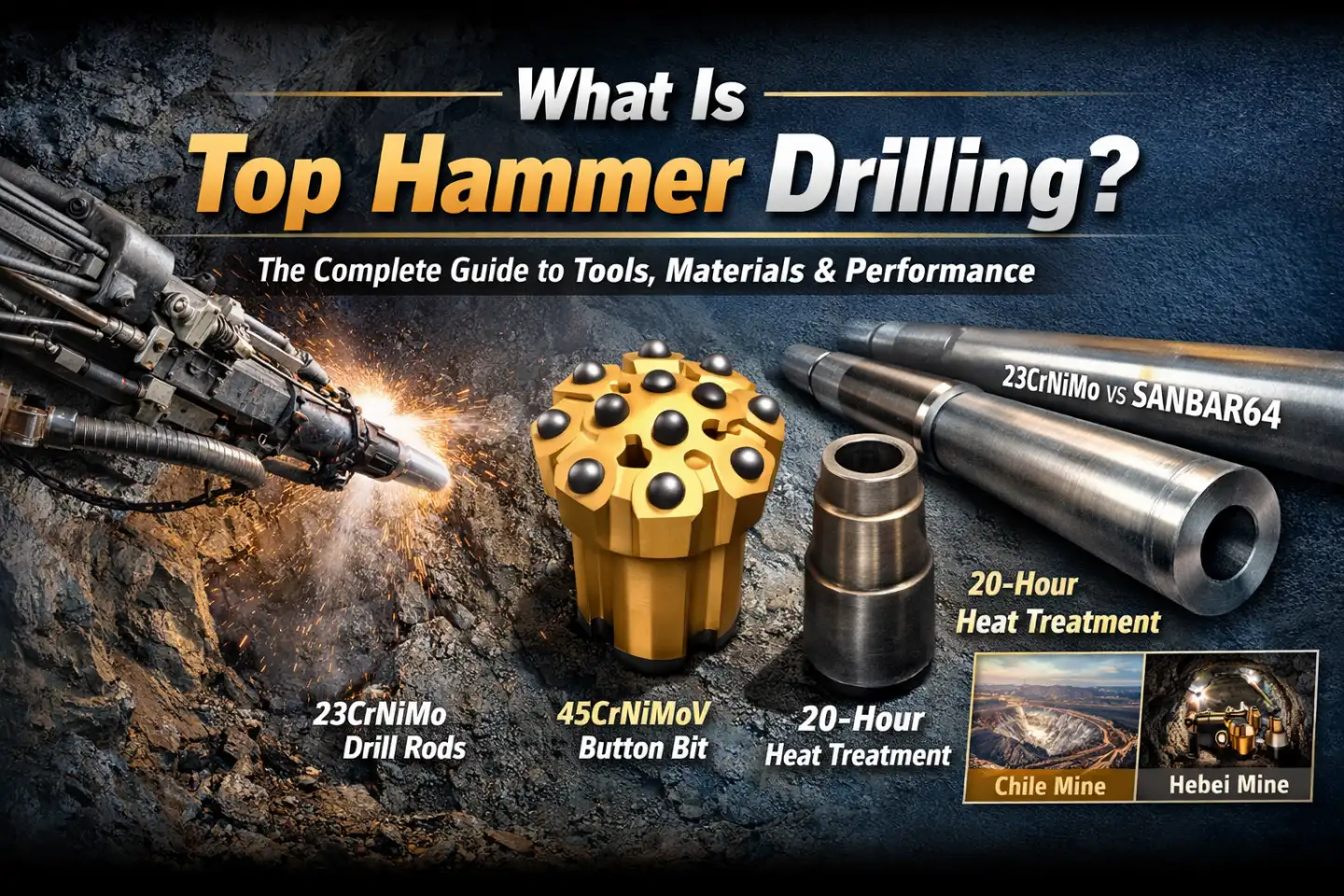
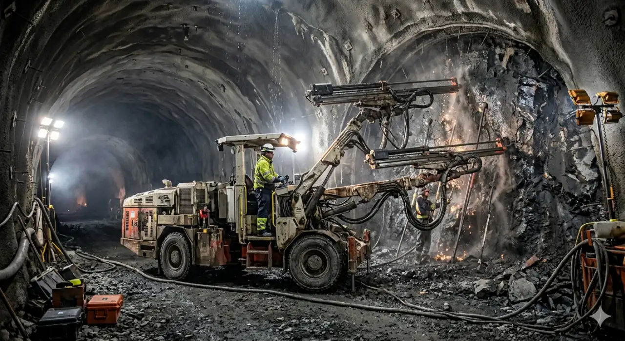
Hydraulic jumbos are the standard here. A two- or three-boom electric-hydraulic jumbo can cover a full-face blast pattern in one setup. The rock drills on these machines run at 2,000–5,000 impacts per minute, generating the high-frequency energy needed to break through hard or medium-hard rock at the face. The drill string — shank adapter, coupled extension rods, and a button bit at the tip — transmits that energy across depths up to 20–30 meters per hole before deviation becomes a practical problem.
Bit selection depends on rock type. Ballistic buttons work well in softer, more plastic rock. Spherical buttons hold up better in abrasive, high-strength formations where flat wear is the main failure mode. For diversion tunnels driven through granite, basalt, or diorite — common lithologies at dam sites in mountainous terrain — spherical button bits on T38 or T45 threaded systems are a common starting point.
Hole diameter for face drilling in a diversion tunnel typically runs 43–51 mm. The cut pattern — whether parallel cut, V-cut, or burn cut — determines how the round breaks and how clean the profile is. Smooth blasting at the perimeter limits overbreak, which matters both for tunnel support costs and for long-term hydraulic efficiency once water is flowing.
| Product Name | Diameter | Buttons (No. x Size mm) | Gauge Angle | Thread | Weight (kg) | Product Code | ||
|---|---|---|---|---|---|---|---|---|
| mm | inch | Gauge | Center | |||||
| T38 Retrac Button Bits For Bench Drilling | 76 | 3 | 8 x 11 | 6 x 10 | 35° | T38 | 3.3 | 174-7614-7605 |
| 76 | 3 | 8 x 11 | 6 x 10 | 40° | T38 | 2.7 | 174-7614-7664 | |
| 76 | 3 | 8 x 11 | 6 x 10 | 35° | T38 | 2.4 | 176-7614-7605 | |
| 76 | 3 | 8 x 11 | 6 x 10 | 35° | T38 | 2.5 | 176-7614-7665 | |
| T38 Standard Button Bit For Bench Drilling | 76 | 3 | 7 x 12 | 4 x 11 | 35° | T38 | 2.4 | 175-7611-7605 |
| 76 | 3 | 8 x 11 | 6 x 10 | 35° | T38 | 3.3 | 173-7614-7605 | |
| 76 | 3 | 8 x 10 | 6 x 10 | 40° | T38 | 3.4 | 173-7614-7664 | |
| 76 | 3 | 8 x 11 | 6 x 10 | 30° | T38 | 3.3 | 173-7614-7603 | |
| T38 Thread & Retrac Bit (64-76mm) | 64 | 2 1/2 | 6 x 12 | 3 x 11 | 30° | T38 | 1.9 | 173-6409-7663 |
| 70 | 2 3/4 | 8 x 10 | 6 x 10 | 35° | T38 | 2.3 | 173-7014-7665 | |
| 76 | 3 | 7 x 12 | 4 x 11 | 35° | T38 | 3.3 | 173-7611-7665 | |
| 64 | 2 1/2 | 6 x 12 | 3 x 11 | 30° | T38 | 1.7 | 173-6409-7603 | |
| 70 | 2 3/4 | 8 x 10 | 6 x 10 | 35° | T38 | 2.0 | 173-7014-7605 | |
| T45 Thread & Retrac Bit For Sale | 76 | 3 | 7 x 12 | 4 x 12 | 35° | T45 | 2.8 | 173-7611-7765 |
| 89 | 3 1/2 | 8 x 12 | 4 x 12 | 35° | T45 | 3.8 | 173-8912-7765 | |
| 76 | 3 | 8 x 11 | 6 x 10 | 35° | T45 | 3.0 | 174-7614-7705 | |
| 89 | 3 1/2 | 8 x 12 | 6 x 11 | 35° | T45 | 4.7 | 174-8914-7705 | |
Further Reading on This Site
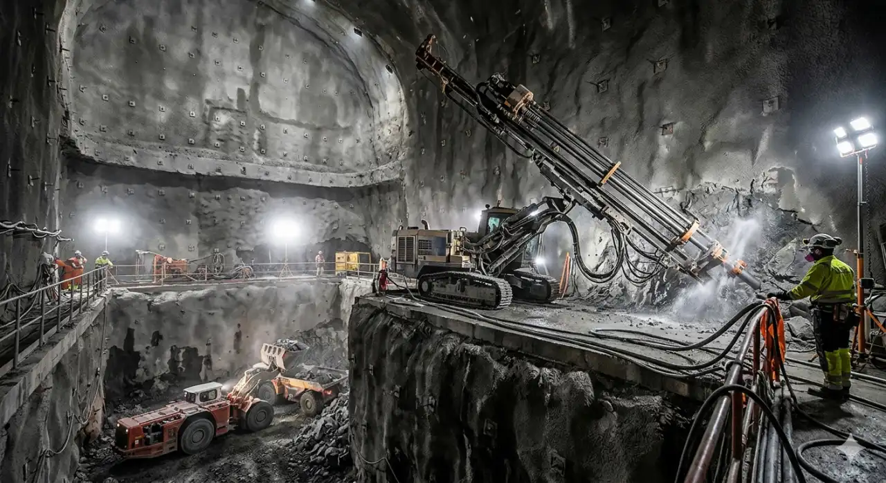
Powerhouse Cavern Excavation
An underground powerhouse cavern is a different challenge from a tunnel. The cross-section is large — widths of 20–30 meters and heights of 40–60 meters are not unusual on major projects. You cannot blast the whole thing in one round. The work goes in stages: a pilot heading at the crown, then successive bench blasts working downward, with support installed between each lift.
Top hammer long-hole rigs handle the production drilling on these benches. Holes of 64–89 mm diameter, drilled downward in fans or rows, define each blast volume. The charge geometry controls fragmentation, which matters because the muck has to be loaded and hauled out through the access tunnel. Fine fragmentation improves loader productivity; too coarse and cycle times suffer.
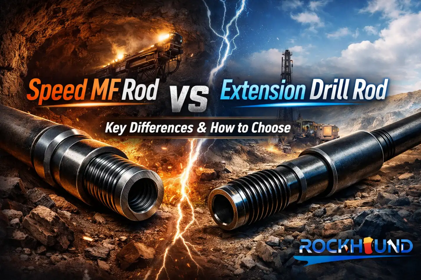
Accuracy is the main technical issue in cavern bench drilling. A 20-meter hole that wanders 1–2 degrees off design can land outside the blast boundary. Over a large cavern with hundreds of production holes, that deviation accumulates into profile problems and irregular walls. Drill rods with precision-machined threads and stiff centralizers help maintain straightness. On long-hole work inside underground caverns, many crews move to guide tubes or MF-thread rod systems specifically to reduce angular deviation over depth.
On a large powerhouse cavern, the excavation cycle is continuous — drilling, blasting, mucking, support, back to drilling. The tools need to keep up with that pace across every shift, not just perform well on the first hole of the day.
Wall control blasting — presplit or smooth blast lines at the perimeter — uses lighter, closely spaced holes to leave a clean, stable rock surface. These holes are smaller in diameter (38–45 mm) and drilled with precise angular control from the jumbo boom. The finished wall becomes the substrate for shotcrete and systematic bolt installation, so its quality directly affects ground support costs.
Systematic Rock Bolting
Underground openings in rock need support. In hydropower caverns and tunnels, systematic rock bolting — installing bolts in a regular grid pattern across the entire excavated surface — is the primary method. Bolt spacings of 1.5–3 meters are typical, with bolt lengths ranging from 3 meters in good rock to 9 meters or more in weaker ground or near fault zones.
Rock bolt installation starts with drilling the bolt hole to the correct angle and depth. Most bolt hole work runs 38–45 mm diameter. The drilling happens right after each blast round, often with the same jumbos used for face drilling, switching to a shorter rod string and a smaller bit. On larger projects, dedicated rock support rigs handle this work separately to keep the face-drilling equipment moving.
Hole straightness matters for bolt installation. A bent or deviated hole can make it impossible to insert a full-length bolt, wasting both time and materials. Drill rods with tight tolerance threads and flush-joint design reduce this risk. Some projects specify resin-anchored bolts that require clean, dry holes — in those cases, the bit type and flushing system need to be matched carefully to the ground conditions and the drilling fluid available on site.
Cable bolt drilling is a step up from standard rock bolting. Cable bolts, used in high-stress zones around cavern walls or at intersections, require longer holes — 10–30 meters — and tighter positional tolerance. This is where top hammer long-hole rigs take over from jumbos. The same principles apply: consistent energy transmission, good flushing to keep the hole clean, and rods stiff enough to track straight over depth.
Drainage Curtain Drilling
Water pressure is one of the main threats to a dam’s stability. When joints and fractures in the foundation rock fill with pressurized water, the effective stress on the rock mass drops, and the risk of sliding or wedge failure increases. The standard engineering response is a drainage curtain: a row of drilled holes behind the grout curtain that intercept pressurized water and drain it to a collection gallery before it can build up stress.
Engineering guidelines from FERC specifically identify abutment joint drainage as an effective method for increasing wedge stability in dam structures — though the drains require regular maintenance to stay functional.
Drainage curtain holes are typically 76–115 mm in diameter, drilled at controlled angles from drainage galleries inside the dam foundation. Depths range from 20 to 80 meters depending on the dam height and the depth of the permeable zone. Positional accuracy is critical — a drainage hole that misses its intended zone provides no protection.
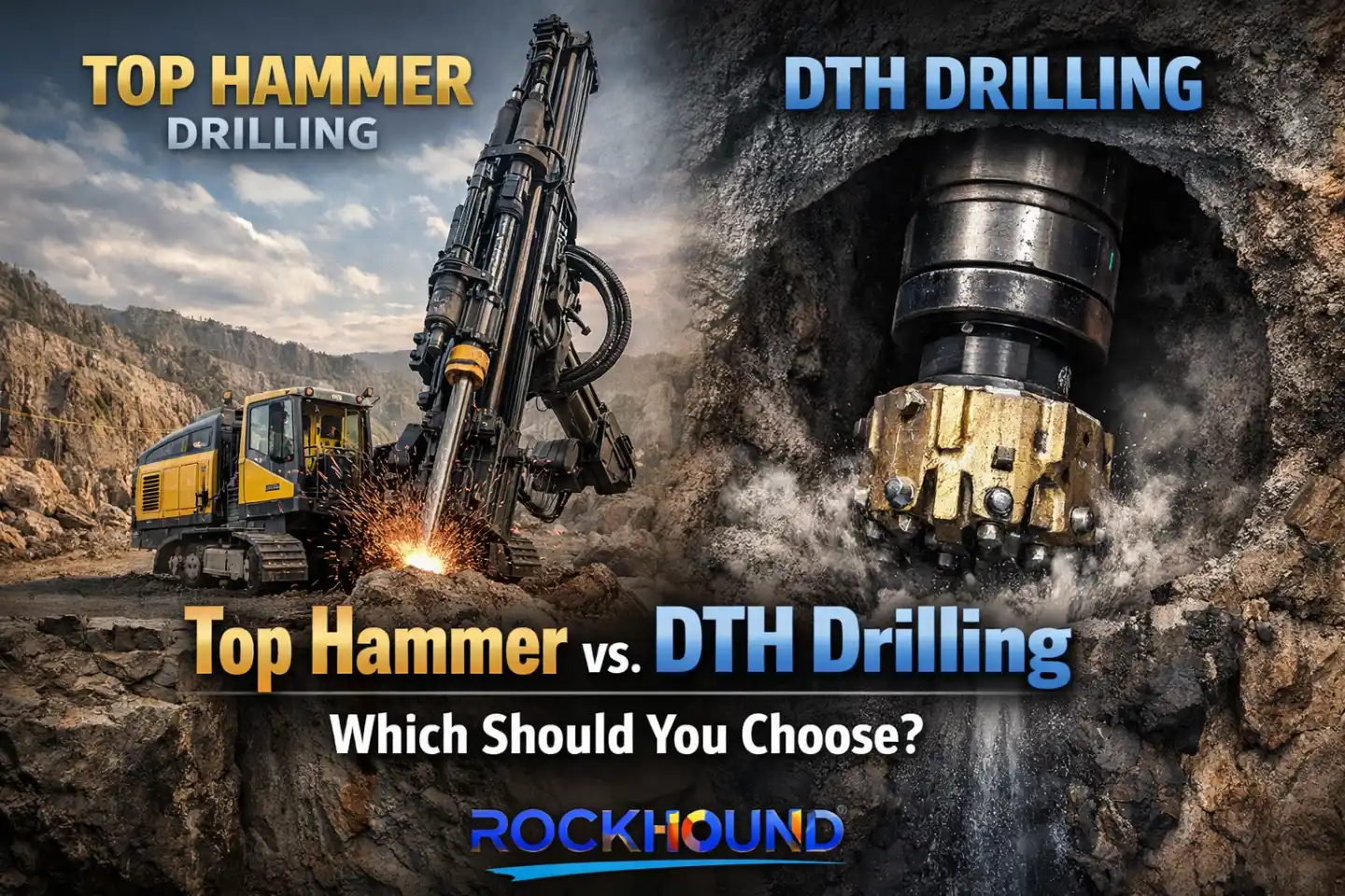
Top hammer drilling handles the shorter holes in this application. Longer, deeper drainage holes often move to DTH (down-the-hole) equipment because DTH maintains consistent impact energy regardless of depth, improving straightness and penetration in very hard rock. The two methods are often used together on the same project: top hammer for the shallower reaches where its high surface power is an advantage, DTH for the deeper perimeter.
Grouting holes — which form the grout curtain that the drainage system backs up — are drilled to similar depths and diameters. The drilling sequence typically goes grout curtain first, drainage curtain second, working from the upstream side toward the downstream face of the dam.
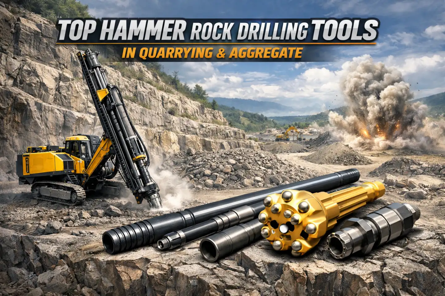
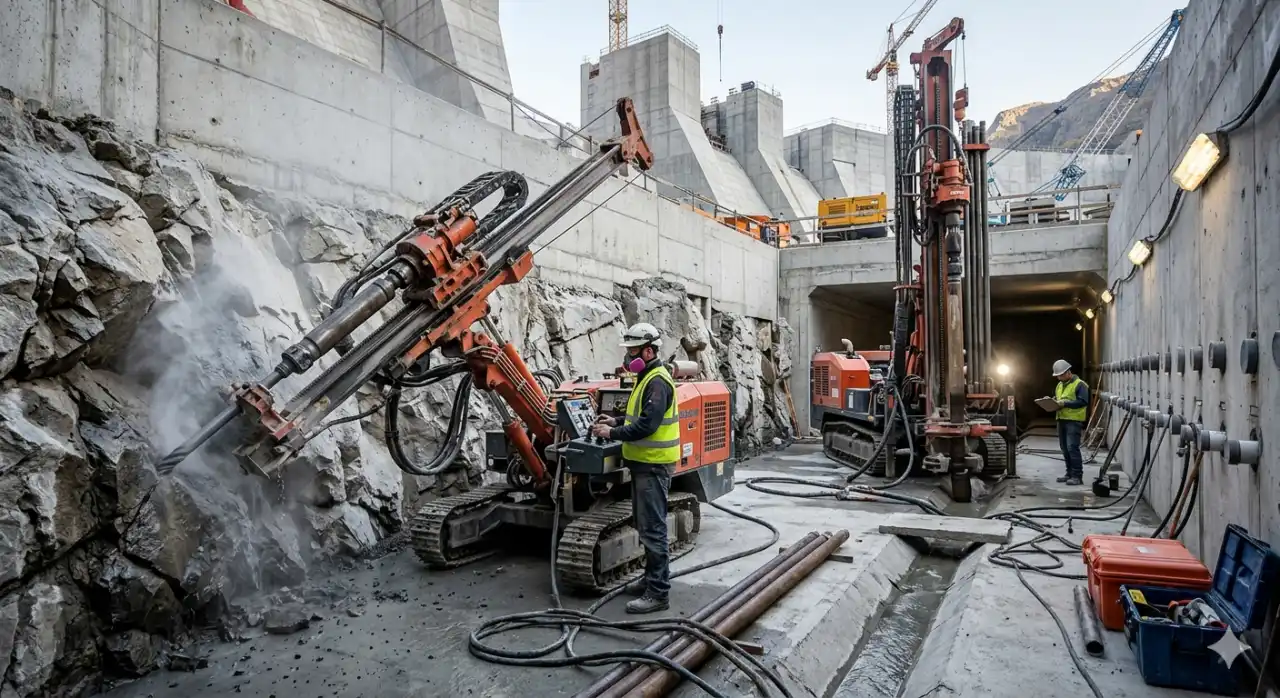
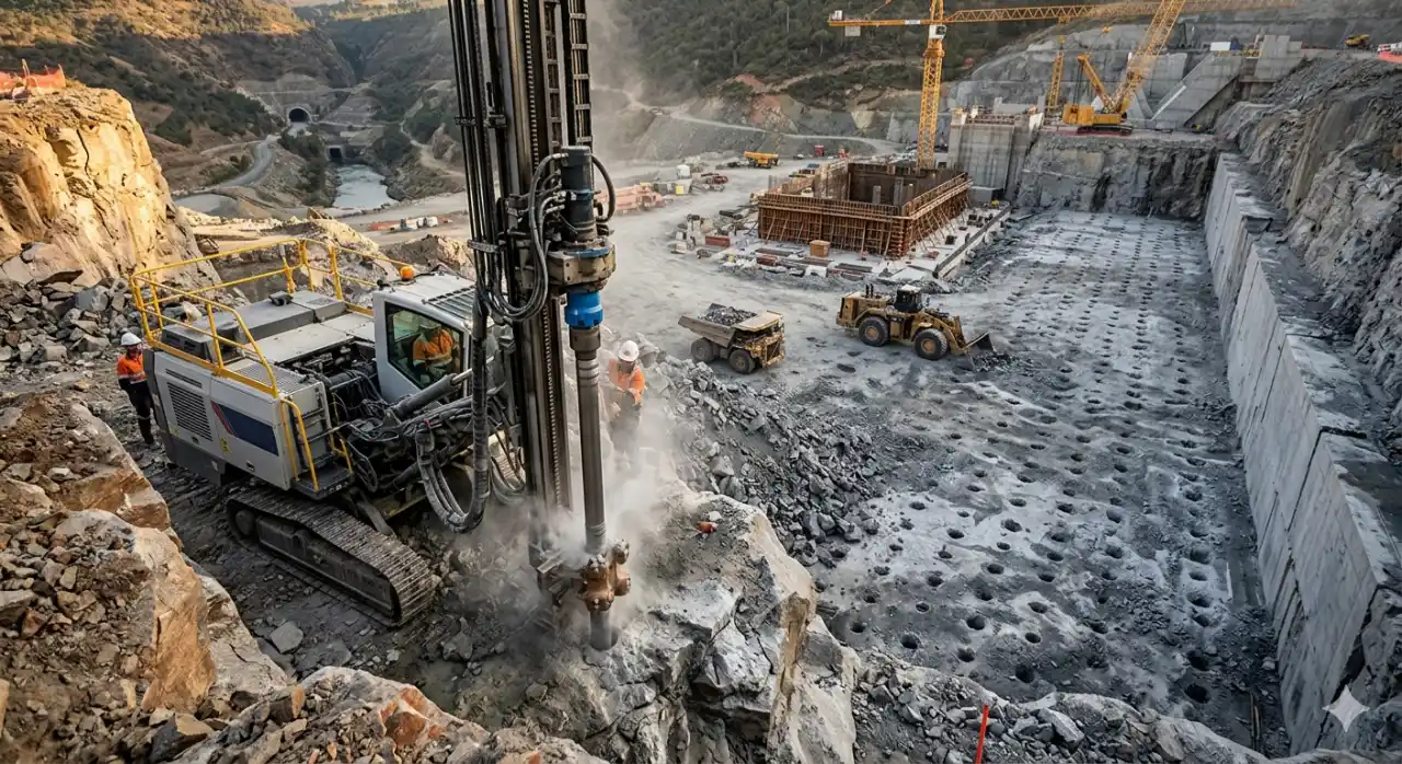
Large-Diameter Bench Blasting at Dam Foundations and Spillways
Before concrete goes down, the rock surface has to be clean and at the right elevation. Dam foundation excavation removes overburden and weathered rock to reach competent, load-bearing material. Spillway channels cut wide, flat profiles into valley walls to pass flood flows safely. Both require large-volume rock removal on a tight schedule.
Large-scale bench blasting with top hammer equipment is the efficient answer. Surface crawler rigs fitted with high-power hydraulic rock drills drill 89–127 mm diameter holes in a bench pattern. Bench heights typically run 10–15 meters on dam foundation work. The pattern geometry — burden, spacing, subdrill depth — is designed to fragment the rock thoroughly while keeping vibration levels within the limits set for nearby structures and fresh concrete.
Pre-split blasting runs ahead of the main production blast to define the final excavation line. A row of lightly charged, closely spaced holes creates a fracture plane that the production blast breaks to without damaging the rock beyond the design boundary. This technique is standard practice wherever the finished rock surface matters — which, at a dam foundation, is everywhere.
Related Articles
The tools used here — T51, T60, or R38/R32 threaded systems depending on rig specification — need to handle the abrasive conditions typical of hard crystalline rock at high-elevation dam sites. Tungsten carbide button geometry on the drill bit is chosen for the specific rock type: aggressive ballistic inserts for softer sedimentary formations, tougher spherical or semi-ballistic profiles for granite and quartzite where insert fracture is a risk.
Penstock Shafts and Inclined Adits
Water moves from the reservoir to the turbines through the penstock — a shaft or tunnel that can be nearly vertical, steeply inclined, or horizontal depending on the site topography. Drilling for penstock shaft construction combines face-drilling techniques at the heading with raise boring for pilot holes and reaming passes.
Top hammer equipment handles the drill-and-blast work in the adit sections and any access headings. The same jumbo tools used in the diversion tunnel work — T38 or T45 extension rod systems, spherical button bits — apply here. The challenge is geometry: penstock sections often have curves and changes of gradient that require careful boom positioning and drill angle control to hold the design line.
Rock support work in penstock tunnels follows the same systematic bolt installation approach described for powerhouse caverns, with bolt patterns adjusted to the local rock mass quality. Where rock conditions are poor, forepoling or spiling — driving steel rods or tubes ahead of the face through the rock — provides temporary support. Top hammer drilling equipment is used for spiling holes as well, typically with smaller casing or tube systems that advance ahead of the excavation.
Tool Selection Reference: Top Hammer Applications in Hydropower
The table below summarizes typical tool specifications across the main drilling applications in a large hydropower project. These are starting-point ranges — actual specification depends on rig model, rock properties, and hole accuracy requirements at each site.
| Application | Drilling Method | Hole Ø (mm) | Typical Depth (m) | Recommended Thread System | Key Tool Requirement |
|---|---|---|---|---|---|
| Diversion tunnel drifting — face drilling | Hydraulic jumbo, top hammer | 43–51 | 3–6 per round | T38, T45 | High penetration rate; spherical button for hard rock; good flushing |
| Cavern excavation — production bench holes | Long-hole top hammer rig | 64–89 | 15–30 | T45, T51 | Hole straightness; stiff rod string; consistent coupling alignment |
| Cavern wall control (presplit/smooth blast) | Hydraulic jumbo, top hammer | 38–45 | 5–15 | T38 | Tight angular control; uniform diameter along hole |
| Systematic rock bolting — bolt holes | Jumbo or dedicated bolter | 38–45 | 3–9 | T38, R32 | Consistent hole depth; clean cuttings removal; flush joint rods |
| Cable bolt drilling | Long-hole top hammer rig | 51–64 | 10–30 | T45, MF series | Low deviation; MF-thread rods for improved stiffness at depth |
| Drainage curtain drilling | Top hammer / DTH | 76–115 | 20–80 | T51, T60 / DTH | Positional accuracy; flush system to clear fine cuttings |
| Dam foundation bench blasting | Surface crawler, top hammer | 89–127 | 10–15 per bench | T51, T60, R38 | High-power rock drill; wear-resistant buttons; pre-split capability |
| Spillway excavation | Surface crawler, top hammer | 76–102 | 8–15 per bench | T45, T51 | Wide pattern drilling; reliable feed performance; long bit life |
| Penstock adit & tunnel face drilling | Hydraulic jumbo, top hammer | 43–51 | 3–5 per round | T38, T45 | Precise angular positioning; smooth bore for flushing in inclined sections |
What Drives Tool Wear and Failure on Hydropower Sites
Hydropower sites are not kind to drilling tools. The rock is often hard — granite, basalt, quartzite, and gneiss are common at high-elevation dam sites in Asia, South America, and Africa. Groundwater is nearly always present, sometimes under significant pressure. Worksites are remote. Getting replacement tools to site takes time, which means every premature tool failure costs more than just the tool price.
Button bit wear is the primary failure mode in hard rock. Tungsten carbide inserts wear flat, which reduces penetration rate and increases drill string stress. Insert fracture happens in highly abrasive rock or when the bit hits an unexpected hard inclusion. Regrinding buttons before wear becomes severe extends bit life significantly — many large hydropower projects have an on-site grinding facility specifically for this purpose.
Rod fatigue is the other major cost driver. Drill rods fail at the thread zone, where stress concentrations are highest during each impact cycle. Using rods with matched thread tolerances and applying the correct thread grease reduces this. Mixing rods from different manufacturers — a common practice when replacement parts are sourced from multiple suppliers — can cause thread mismatch that accelerates failure.
Shank adapters see both impact stress and rotational torque. They typically need replacement before other components. Monitoring shank adapter wear as a leading indicator of rig setup quality — percussion pressure, feed force, rotation speed — helps teams catch adjustment issues before they spread wear to the more expensive rod string.
FAQ
Hydraulic two- or three-boom jumbos are the standard for diversion tunnel drifting. They carry hydraulic top hammer rock drills that operate at 2,000–5,000 impacts per minute and can cover a full-face drill pattern in a single setup. The drill string normally uses T38 or T45 threaded extension rods with spherical button bits in hard rock. A complete blast round in a 40–60 m² tunnel face typically runs 3–5 meters of advance per cycle.
After each excavation lift is blasted and mucked, bolt holes are drilled in a regular grid pattern — typically 1.5–3 m spacing — across the newly exposed rock surface. Holes are usually 38–45 mm in diameter and 3–9 m deep. The same jumbo used for face drilling can do this work by switching to a shorter rod string. In major caverns, a dedicated rock support rig handles bolt drilling separately so the main excavation cycle is not interrupted. Cable bolts, for higher-stress zones, require longer holes of 10–30 m and often use MF-thread rod systems for better straightness at depth.
A drainage curtain is a row of drilled holes installed behind a dam's grout curtain to intercept water under pressure in the foundation rock and carry it away through a drainage gallery. This prevents the buildup of uplift pressure that could destabilize the dam or its abutments. The holes are typically 76–115 mm in diameter and can reach 20–80 m deep depending on the dam's height and the depth of the permeable rock zone. Positional accuracy is critical — a hole that misses its target zone provides no drainage benefit. Shorter holes use top hammer drilling; deeper holes often require DTH equipment to maintain straightness and consistent energy at depth.
Dam foundation and spillway bench drilling typically uses T51 or T60 threaded rod systems paired with surface crawler rigs that carry high-power hydraulic rock drills. Hole diameters run 89–127 mm with bench heights of 10–15 m. The bit insert geometry is chosen for the specific rock — spherical or semi-ballistic tungsten carbide buttons for hard granitic rock, more aggressive ballistic profiles in softer sedimentary formations. Pre-split holes for wall control use the same equipment but run smaller-diameter bits at tighter spacing to define the final excavation boundary cleanly.
In top hammer drilling, the rock drill sits at the top of the drill string and impact energy travels down through the rods to the bit. This setup offers very high penetration rates and lower equipment cost, and works well for holes up to 20–30 m in medium-hard to hard rock. Energy loss through the rod string increases at greater depths, which limits both penetration rate and hole straightness. DTH drilling places the hammer directly behind the bit at the bottom of the hole, so impact energy does not travel through the rods — this maintains consistent performance and better hole straightness at depths beyond 30 m. Hydropower projects typically use both: top hammer for face drilling, bench drilling, and bolt holes; DTH for the deeper drainage curtain and grouting holes.
The main cause is abrasion from hard, silica-rich rock types common at dam sites — granite, quartzite, gneiss, and basalt. Tungsten carbide button inserts wear flat, reducing penetration rate and increasing stress on the bit body and rods. Operating with worn buttons accelerates insert fracture and damages the bit face. Other contributors include mismatched thread tolerances when rods from different suppliers are mixed, insufficient or incorrect thread lubrication, and running percussion pressure or feed force above the rock drill manufacturer's recommended range. Regrinding buttons at the right wear interval — before flat wear exceeds 1/3 of insert diameter — is the most cost-effective way to extend bit life in hard rock conditions.
Yes. Top hammer hydraulic rock drills are capable of drilling rock with UCS values well above 200 MPa when the correct bit geometry and rod system are used. The key is matching button insert grade to rock abrasivity — in very hard, abrasive rock, a tougher carbide grade with spherical button geometry resists wear and fracture better than softer grades with ballistic profiles. High-frequency impact energy from a hydraulic rock drill running at full power also maintains penetration rates in hard rock that pneumatic machines cannot match. The limit is not rock hardness but hole depth: beyond 25–30 m, deviation and energy loss in the rod string begin to outweigh the speed advantage, and DTH becomes the better choice.