Table of Contents
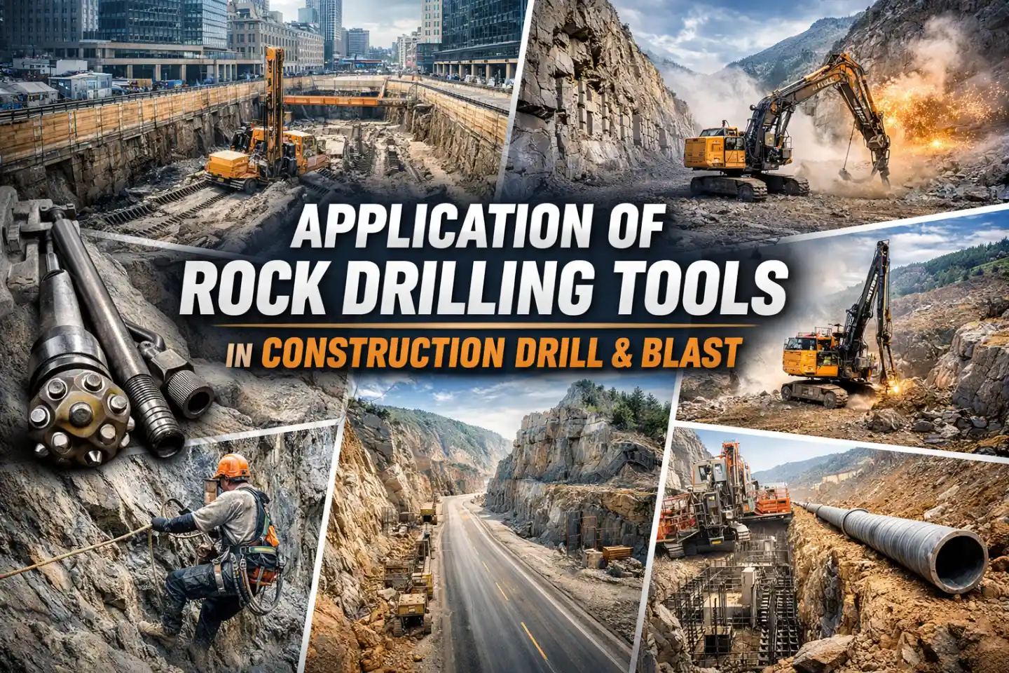
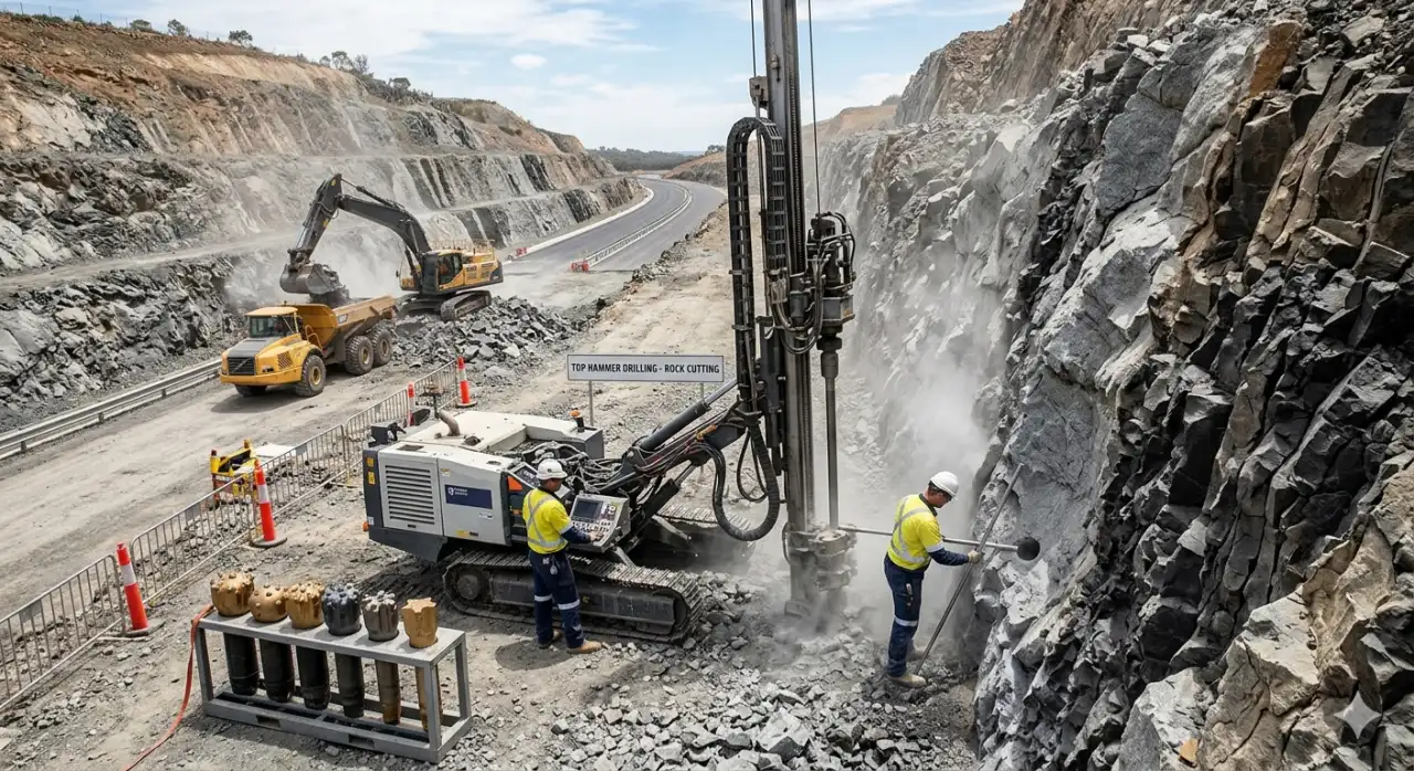
Modern infrastructure and civil earthworks are hitting harder rock than ever before. To keep projects on schedule while maintaining safety, site managers are turning to controlled drill-and-blast techniques. At the heart of these operations are top hammer drilling tools. Whether it is foundation drilling in a city center or rock slope stabilization for a new highway, the choice of hammer and bit determines your cost-per-meter.
RockHound provides the specialized tool systems needed to transition between light and medium-duty work with surgical precision. This guide looks at how these tools perform in the most demanding construction environments.
Why Top Hammer Still Dominates Construction Drilling
Before getting into specific applications, it helps to understand why top hammer remains the go-to method for most construction drill and blast work.
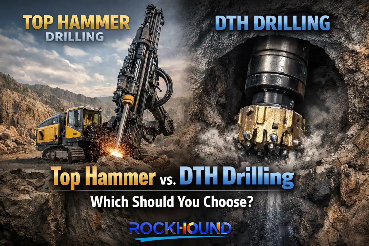
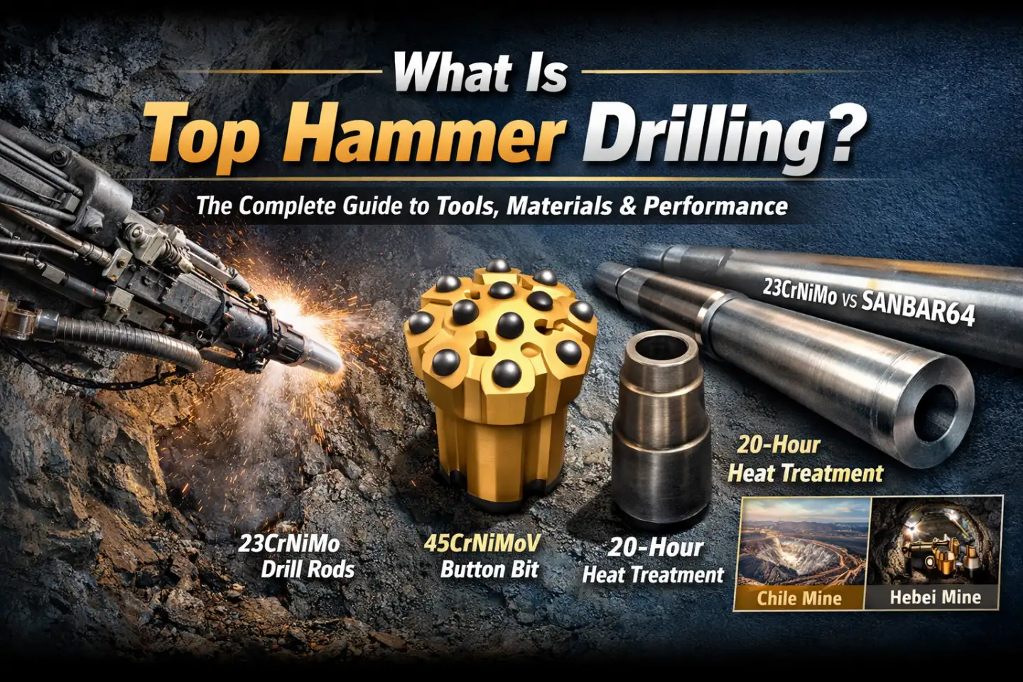
In top hammer drilling(What Is Top Hammer Drilling? The Complete Guide), the hammer produces a percussive force on the drill rods or tubes, which is transmitted to the drill bit. The percussive system can deliver 2,000–5,000 strikes per minute, with rotation speeds between 60 and 200 rpm.That combination of impact and rotation breaks rock efficiently without requiring the downhole components that make DTH systems heavier and more complex to service(Related Reading: Top Hammer Drill vs DTH Drilling:Which To Choose).
In 2026, top hammer drilling technology remains one of the most economical and efficient solutions for shallow-to-medium depth rock drilling, with advantages including high penetration rates, precise hole control, and relatively low operational costs.
For construction projects specifically, these traits translate directly into schedule control and cost predictability — two things contractors need most.
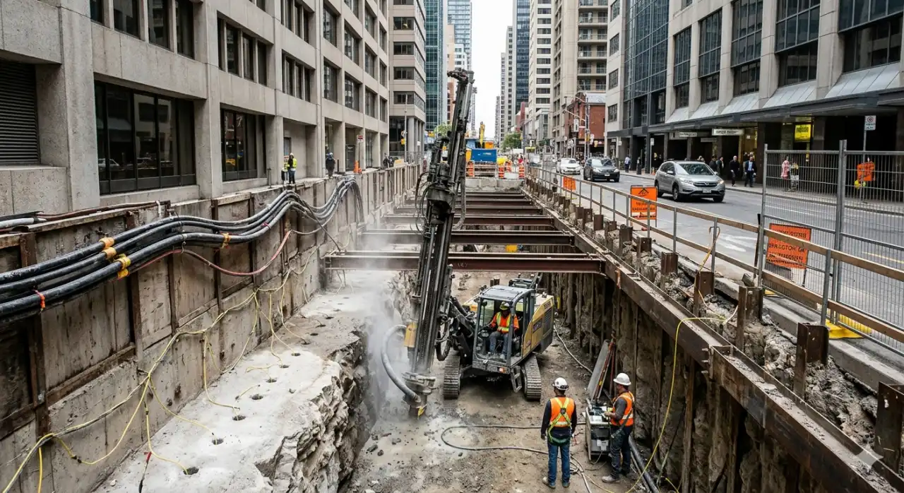
Urban Cut-and-Cover: Working Inside the City
Cut-and-cover construction — used widely for subway stations, underpasses, and utility corridors — puts drilling crews into some of the tightest, most regulated environments imaginable. The excavation site is often wedged between occupied buildings, live road infrastructure, and underground utilities. Traditional open blasting is rarely an option.
The Vibration Problem
Blasting generates ground-borne vibration with frequencies from 1 to 300 Hz and peak particle velocity (PPV) up to 50 mm/s. This can significantly impact nearby structures, especially those resonating at frequencies of 6–10 Hz. Air overpressure from explosions — with frequencies as low as 40 Hz — can damage building windows and facades.
In practice, urban blasting projects rarely get anywhere near 50 mm/s. Regulatory limits in dense urban zones typically cap PPV at 2–5 mm/s near historic structures and 10–25 mm/s near standard residential buildings. Staying inside those thresholds requires smaller charge sizes per hole — and smaller charge sizes require smaller hole diameters. Most urban cut-and-cover projects keep blast holes between 32 and 48 mm.
That range is exactly where top hammer tools perform best. A well-configured rig with the right shank adapter, drill rod, and button bit can drill a 38 mm hole through sandstone or limestone faster than any alternative method at those depths. More importantly, the rig can be repositioned quickly between blast rounds, which is critical in urban environments where you’re often drilling in one narrow section of the site while another section is in lockdown for a blast sequence.
Urban Controlled Blast: The Technical Approach
Urban controlled blast is not just about reducing powder factor. It requires a coordinated strategy across hole pattern design, initiation timing, and real-time PPV monitoring.
The most effective approach combines three elements. First, hole diameters are kept small (32–51 mm) to limit the maximum charge per hole. Second, millisecond-delay electronic detonators are used to ensure only one or two holes fire at any given millisecond window — keeping instantaneous charge weight low. Third, pre-split blasting is performed along the final excavation boundary before any production holes are fired.
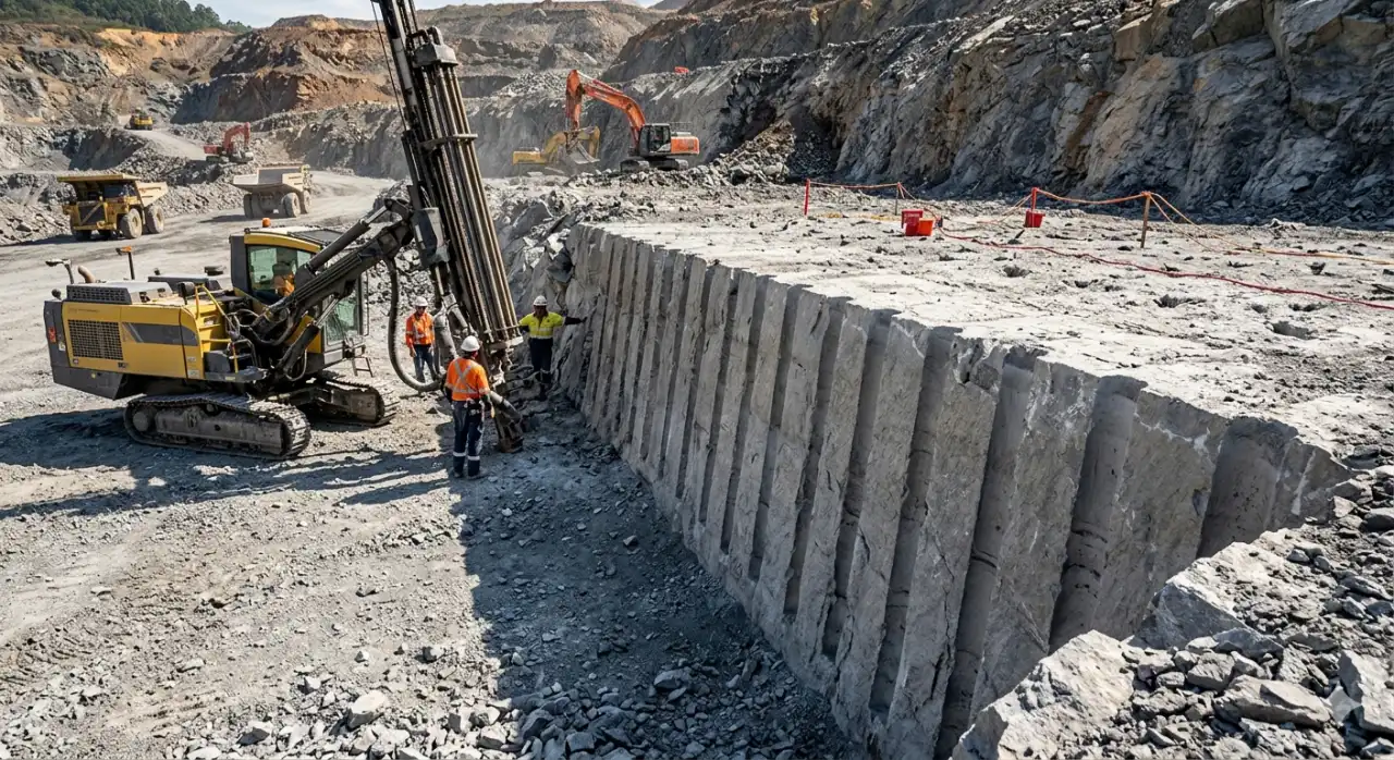
Pre-Split Blasting: Protecting the Final Rock Face
Pre-split blasting is the technique that separates competent final walls from fractured, unstable ones. Done correctly, it defines the exact boundary of excavation before the main blast ever fires — and it does so by creating a continuous fracture plane that the production blast cannot penetrate.
The method involves drilling a line of closely spaced holes (typically 8–12 times the hole diameter in center-to-center spacing) along the intended final face, then firing them simultaneously or with very short delays before the production round. The simultaneous firing creates a reflected tensile wave between adjacent holes that propagates a clean crack along the drill line.
What this means practically: the production blast breaks rock up to the pre-split plane and stops. The final rock face retains its original strength and structure. Half-casts — the visible half-cylindrical grooves left by the drill bits in the remaining rock — serve as the quality indicator on site. If the half-casts are clean and continuous, the pre-split worked. If they are absent or broken, the face has been over-blasted and remediation will be needed.
For road construction projects, achieving clean pre-split results also matters for slope aesthetics. Highway departments in many countries now specify minimum half-cast ratios (typically 50–80%) as a contractual requirement, particularly in visible cut slopes along tourist corridors or protected areas.
The tooling requirements for pre-split work are specific. Hole straightness is non-negotiable — even 1–2° of deviation over a 10 m hole causes the drill line to wander, breaks the crack propagation, and defeats the purpose of the technique. This demands stiff, well-matched drill rods and bits with tight dimensional tolerances. For most pre-split applications in construction, T38 or T45 thread systems with extension rods in 3 m or 3.66 m lengths give the right balance of stiffness and manageability.
RockHound T38 Equipment Drilling System
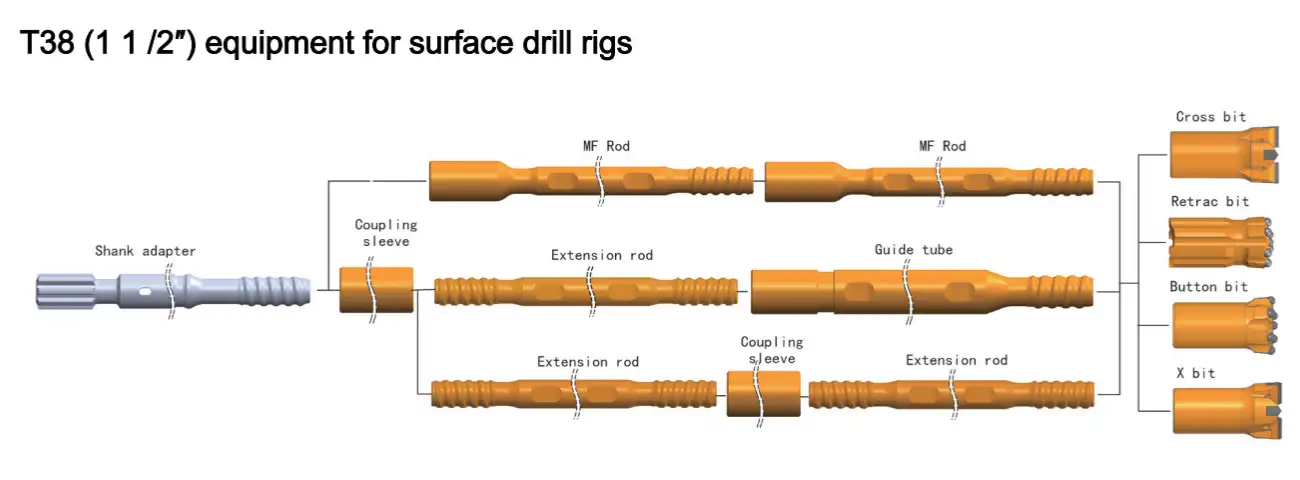
| Rock Drill Bits | Drill Rods | Shank Adapter |
|---|---|---|
T45 Equipment Drilling System
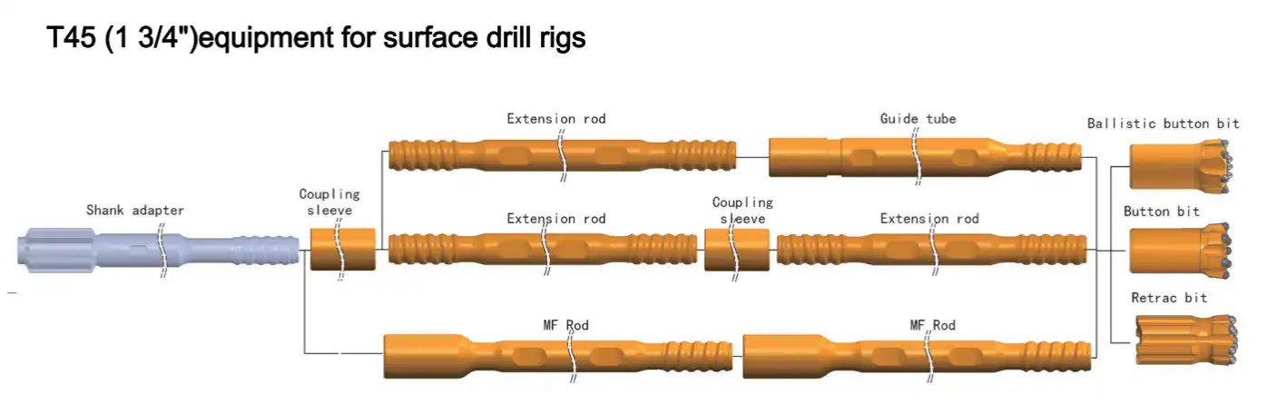
| T45 Retrac Button Bit | T45 Extension Rod | Shank Adapter (Cop Series) |
|---|---|---|
Road Cutting and Highway Excavation
Road cutting — the removal of rock to create a roadway corridor through high terrain — is one of the highest-volume applications for construction drill and blast. It demands consistent throughput day after day, often in variable rock conditions that shift from competent granite to heavily jointed basalt within the same bench.
Production blasting for road cuttings uses bench heights between 5 and 15 m, with hole diameters typically running from 51 to 89 mm. Top hammer excels here: top hammer equipment allows effective drilling to depths of 30 to 40 ft (roughly 9–12 m), and holes drilled by this type of equipment are typically 140 mm and smaller.For road cutting depths in that range, the energy transmission through the drill string is efficient enough to sustain high penetration rates without the complexity and cost of DTH.
Bit selection on road-cutting projects depends heavily on the formation. In hard, abrasive rock — granite, quartzite, tough sandstone — spherical (dome) button bits last significantly longer than ballistic or semi-ballistic designs. The tradeoff is penetration rate: ballistic buttons cut faster in medium-hardness formations but chip and wear rapidly above 150 MPa UCS. Experienced drillers typically test two or three bit profiles at the start of a project and track meters-per-bit rather than relying on supplier recommendations alone.
Collar deviation is the other persistent challenge in road cutting. When the first 0.5–1 m of a hole drifts, the entire hole deviates, and the blast pattern breaks down. Using a guide rod or pilot adapter on the first rod, combined with a flat-face bit for collar work, significantly reduces this problem. Once past collar depth, standard button bits take over.
Foundation Drilling and Rock Anchor Installation
Foundation drilling in urban and civil construction covers a range of activities: anchor hole drilling for tie-back walls, micropile installation, rock socket drilling for bridge columns, and ground anchor work for retaining structures and slope stabilization. These applications share a common demand — the hole must be exactly where the engineer specified, at exactly the right diameter and depth, and the borehole wall must be clean enough for grout or resin to bond properly.
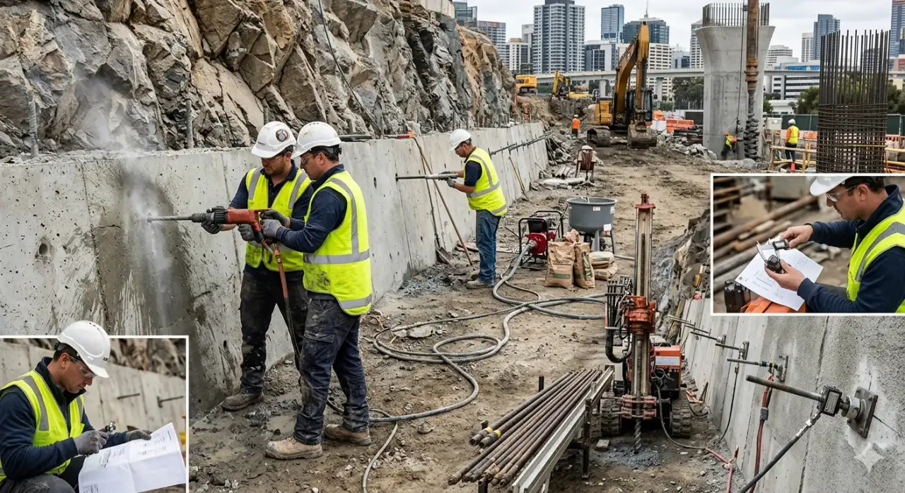
Drilling in the Field
Urban infrastructure and civil earthworks increasingly rely on controlled drill-and-blast techniques facilitated by top hammer tools. Foundation anchor hole drilling, rock slope stabilization, and trench excavation in hard rock formations demand tool systems that can transition between light and medium-duty work with precision. Hand-held air-leg drills and guide-rail pneumatic drills serve small-diameter anchoring applications on vertical or inclined faces — particularly where larger rigs simply cannot reach.
On vertical or near-vertical rock faces, a two-person air-leg crew can drill 32–45 mm anchor holes to depths of 3–6 m with consistent quality, provided the hole is flushed properly between passes. Water flushing is often preferred over dry air in anchor work because it reduces dust exposure and delivers cleaner borehole walls — which matters for grouting. Air flushing alone can leave a fine rock flour coating on the hole walls that reduces bond strength.
For deeper anchor holes (6–15 m) or where hole straightness is critical for pre-stressed tendons, guide-rail mounted drifters on compact carrier rigs offer better performance. The feed rail keeps the drill axis fixed while the rod is extended, preventing the angular drift that happens with hand-held equipment on longer holes.
Anchor Hole Drilling: Tolerances and Consequences
Anchor hole drilling tolerances are tighter than most drilling work. Hole diameter must match the anchor system specification — typically the anchor body diameter plus a grout annulus of 10–15 mm on each side. A 25 mm threaded bar anchor, for example, generally requires a 51 mm borehole. Going under-diameter makes anchor insertion difficult; going significantly over-diameter wastes grout and can affect the bond model the design was based on.
Depth tolerance is equally critical. A hole drilled 300 mm short of the specified embedment length can significantly reduce the anchor’s load capacity — particularly in rock where the bond is concentrated in the fixed length zone. On projects where pull-test verification is required, under-drilled anchors fail the test and have to be re-drilled, adding cost and schedule delay.
Bit wear monitoring matters more in anchor work than in production drilling. A worn button bit produces a slightly under-gage hole, which then requires more force to insert the anchor body. Pulling a slightly oversized anchor through a worn-gage hole damages the grout tube and can compromise the anchor system before it even gets tested. Replacing bits at 1/3 tooth wear — rather than running them to destruction — keeps holes consistent and insertion smooth.
To learn more about how top hammer tools handle heavy-duty drilling tasks, see our overview of the advantages of top hammer drilling tools in mining.
Rock Slope Stabilization: Drilling Under Pressure
Rock slope stabilization work puts drillers in conditions that test both equipment and nerves. The face is unstable by definition — that’s why it needs stabilizing. Work is often done from ropes, scaffolding, or small work platforms on steep terrain. And the consequence of a tooling failure (a stuck drill string, a broken shank adapter, a bit that won’t retract) is significantly more serious than on a flat bench.
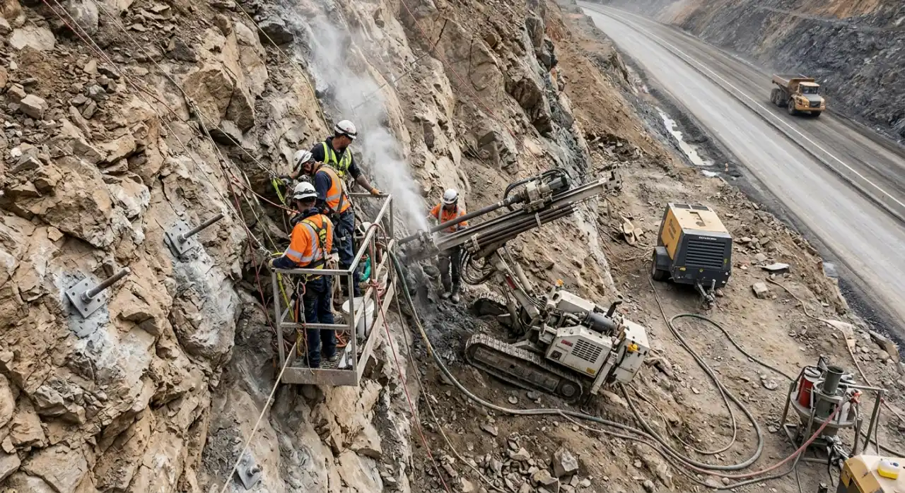
The typical stabilization sequence combines rock bolts or soil nails, shotcrete, and — where specific unstable blocks need to be removed — trim blasting. For the drilling portion, compact top hammer tools win on every metric that matters in this environment: power-to-weight ratio, tool accessibility for maintenance, and compatibility with small pneumatic compressors that can be positioned below the work face.
Rock bolts for slope stabilization are typically installed in 32–45 mm holes at depths of 3–8 m, angled perpendicular to the slope face or oriented to cross the identified failure planes. The drilling needs to be done cleanly — no belling of the collar, consistent diameter through the full depth, thorough flushing before grouting. All three of these requirements favor proper tooling selection over simply running whatever bits are available on site.
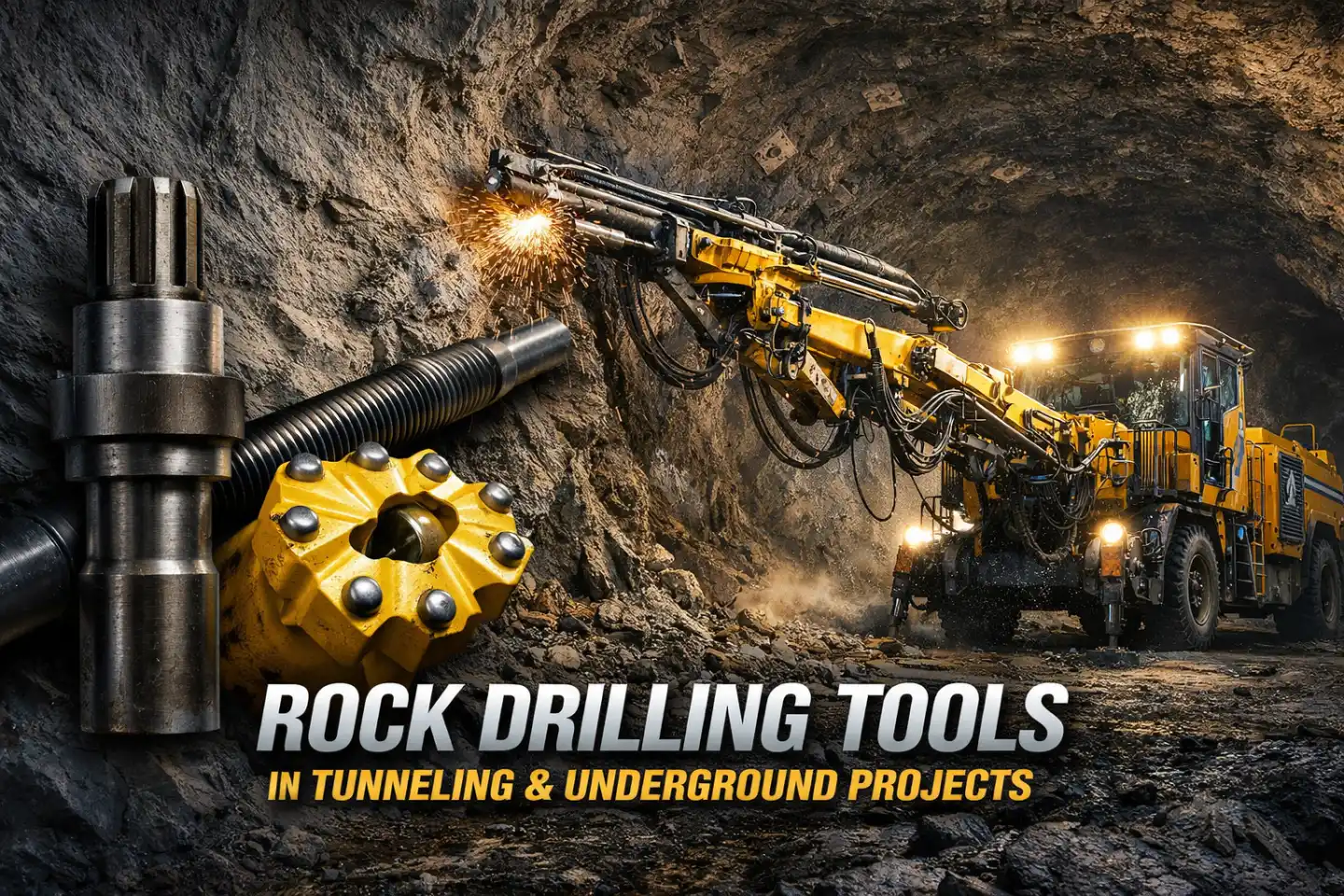
For a broader view of how rock drilling tools apply in underground and constrained environments, see Rock Drilling Tools in Tunneling & Underground Drifting.
Trench Excavation in Hard Rock
Trench blasting for utility lines, drainage systems, and pipeline corridors in hard rock is technically demanding work. The geometry of a trench — narrow width, vertical walls, specific depth — means the blast design has very little room for error. There is no buffer zone between the explosive charge and the final wall on either side.
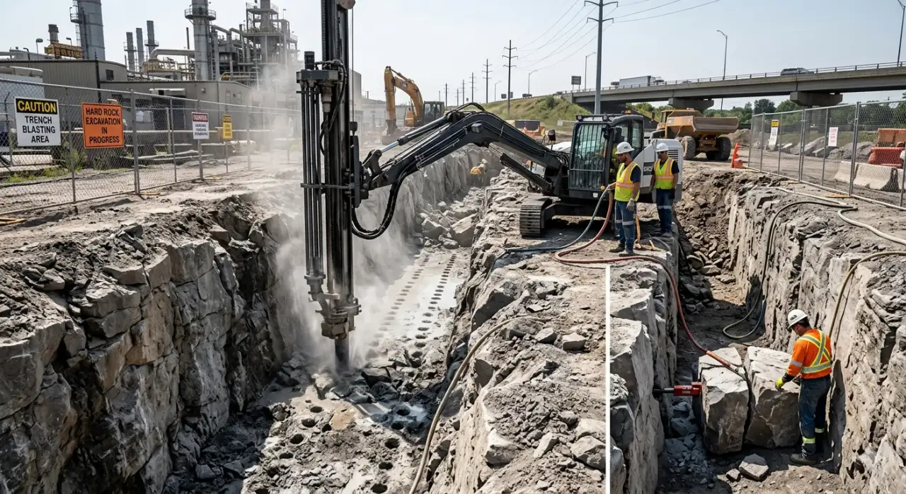
Hole diameters for trench blasting typically run from 32 to 51 mm, with depths matching the trench specification. The two dominant blast patterns are the center-row method (center holes slightly ahead of perimeter holes, with uniform loading) and the smooth-wall method (all holes in one row, with heavier charges in center holes and lighter charges at the walls). The smooth-wall approach gives better wall quality but requires more precise drilling — off-pattern holes result in either a rough wall or a blown-out trench edge.
Where blasting is not possible at all — inside an operating facility, near pressurized pipelines, or beneath live traffic — the trench must be cut mechanically. In those cases, the top hammer drill plays a different but still useful role: drilling a series of guide holes along the trench line that define the excavation boundary and provide slots for hydraulic splitter insertion. The same tooling, repurposed for a non-explosive method.
Technical Reference: Tool Selection by Construction Application
The following table summarizes recommended tool specifications across common construction drill and blast scenarios, based on field practice and tooling data from industry sources.
| Application | Typical Hole Diameter | Thread System | Bit Type | Key Performance Factor |
|---|---|---|---|---|
| Urban cut-and-cover | 32–48 mm | R32, R35 | Spherical button | Low vibration, tight pattern tolerance |
| Pre-split blasting | 51–89 mm | T38, T45 | Spherical button | Hole straightness, half-cast ratio |
| Rock anchor installation | 38–64 mm | R28, R32 | Spherical or retrac | Borehole cleanliness, gage consistency |
| Road cutting (bench) | 51–102 mm | T38, T45, T51 | Spherical button (hard rock) | Penetration rate, bit life |
| Slope stabilization | 32–45 mm | R25, R32 | Spherical button | Tool weight, collar accuracy |
| Trench excavation | 32–51 mm | R32, R35 | Retrac | Wall control, easy retraction |
For a full explanation of how different thread systems and tool geometries interact, see What Is Top Hammer Drilling? The Complete Guide.
Practical Notes on Tooling Longevity
Getting more meters out of the same tooling investment is not complicated, but it does require consistent habits on site.
Thread lubrication is the easiest gain. A thin application of proper drill rod grease on both male and female threads before each connection reduces the heat generated at joints, prevents galling, and meaningfully extends shank adapter life. Many sites skip this step when crews are under production pressure — and then wonder why shank adapters are failing every few weeks.
Feed pressure calibration matters just as much. Running too little feed force causes the drill string to bounce, which beats up the shank adapter and produces inconsistent energy transfer to the bit. Too much feed pressure locks the bit against the rock, prevents rotation, and causes glazing — the bit spins on the surface without cutting. The right setting varies by formation and is typically established during the first few holes of each shift, not set once and forgotten.
Retrac bits deserve mention specifically for anchor hole work and trench drilling. Their back-reaming cutting edges allow the bit to cut during withdrawal if the hole collapses or if cuttings pack around the bit body. In fractured formations — common in urban excavations where the rock has been stressed by previous construction or seismic activity — a retrac design can be the difference between recovering a stuck drill string and losing it entirely.
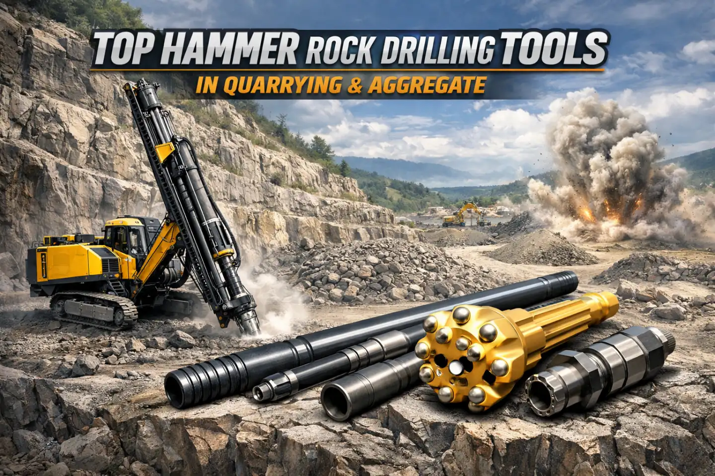
For a detailed look at how these tooling principles apply in aggregate and quarrying operations, see Top Hammer Rock Drilling Tools in Quarrying & Aggregate.
FAQ
Top Hammer is usually best for holes shallower than 20-30 meters and diameters under 127mm. It offers faster penetration in soft-to-medium rock and better fuel efficiency for shallow work.
Beyond using smaller hole diameters and delays, contractors use heavy blasting mats (often made of recycled tires and steel wire) to contain debris.
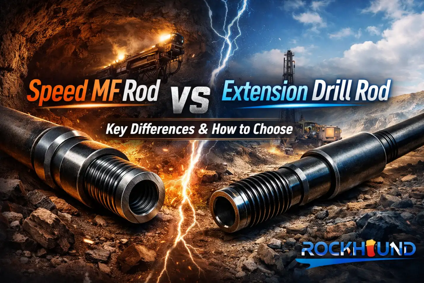
Male/Female (MF) rods eliminate the need for separate coupling sleeves. This creates a more rigid drill string, leading to straighter holes and less energy loss at each joint See More: Rock Drilling Tools In Tunneling and Drifting.
The PPV method, as outlined in DIN 4150-3 and BS 5228-2, measures the highest vibration velocity amplitude in the signal. In practical terms, most urban blast projects target PPV below 5 mm/s near sensitive structures and below 25 mm/s near standard construction. Historical structures and buildings with existing damage surveys often trigger limits as low as 2 mm/s. These limits inform hole spacing, charge weight per delay, and initiation sequence design.
Track wear on the tungsten carbide buttons relative to their original diameter. When wear exceeds one-third of the button diameter, bit performance drops off sharply and the worn profile begins to reflect impact energy back into the drill string rather than into the rock. This accelerates shank adapter and rod wear. A bit that looks close to worn but "still works" is often costing more in tool damage than it would cost to simply replace it.
The pre-split mechanism depends on the tensile wave reflected between adjacent holes propagating along the drill line. If spacing is irregular or holes wander off-angle, the crack propagation is interrupted, and sections of the face receive production blast energy without pre-split protection. The result is over-break, rough wall surfaces, and potential instability. Hole spacing should be held to within ±50 mm of design, and angular deviation should stay under 1° per 3 m of depth.
A retrac bit has secondary cutting edges on the back face of the bit body. During normal drilling, the bit cuts forward as usual. If the hole collapses or cuttings pack tightly during withdrawal, the retrac edges allow the bit to continue cutting on the way out. This prevents the bit — and the connected drill string — from being stuck in the hole. Retrac bits are the standard choice for fractured rock, clay-seam formations, and any application where there is a meaningful risk of hole collapse.