Table of Contents
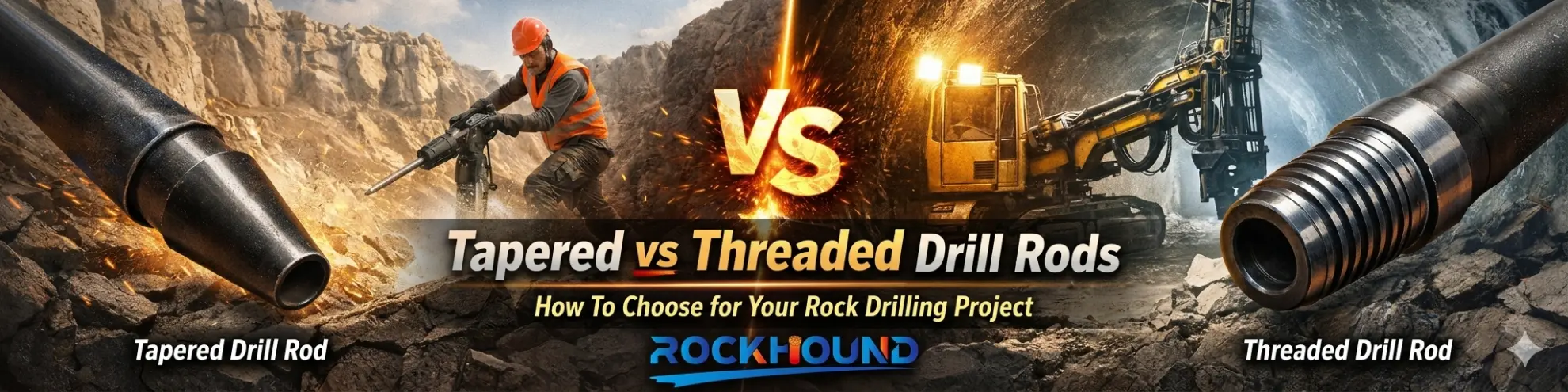
Tapered drill rods are the backbone of hand-held rock drilling systems, widely deployed across mining, quarrying, tunneling, and construction blasting operations. Engineered to transmit percussive energy from the rock drill to the drill bit via a self-locking tapered interface, they offer a decisive operational advantage: rapid bit exchange without threaded connections, making them the tool of choice for light-duty and short-hole applications.
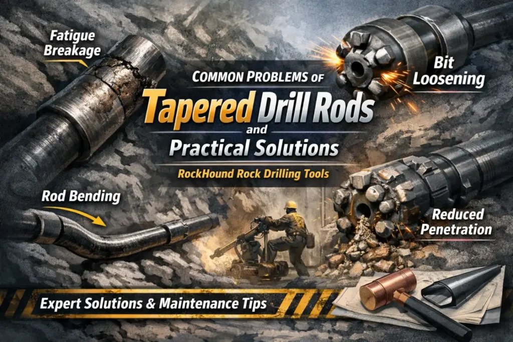
Despite their mechanical simplicity, tapered drill rods are subject to a range of failure modes that — left unaddressed — translate directly into reduced Penetration Rate (PR), increased consumable costs, and costly operational downtime.
At RockHound, we work closely with drilling contractors, mining engineers, and quarry operators worldwide. Based on field data and materials engineering analysis, this guide identifies the five most critical failure modes of tapered drill rods, explains their root causes using precise industry terminology, and provides actionable, field-proven solutions.
Quick Reference: Tapered Drill Rod Failure Modes at a Glance
| Problem | Primary Cause | Professional Term | Quick Solution |
|---|---|---|---|
| Taper Connection Wear | Mismatched angles / Abrasive contamination | Taper Galling / Interface Friction | Match 7°/11°/12° taper angles; clean taper surfaces thoroughly before assembly; apply anti-seize if recommended |
| Rod Bending | Excessive feed pressure / Poor collaring | Axial Deviation / Buckling Stress | Reduce feed force at start; use starter rod or guide tube; ensure proper alignment and collaring technique |
| Drill Bit Loosening | Insufficient pre-seating / Worn taper surfaces | Taper Slippage / Lost-in-Hole | Pre-seat bit with copper mallet or light hammer blows; replace worn taper components immediately; check taper condition regularly |
| Rod Breakage | Metal fatigue / Blank firing / Corrosion | Fatigue Crack Propagation / Percussive Fatigue | Avoid blank firing; use premium high-alloy steel rods; inspect threads and body regularly; maintain proper lubrication |
| Reduced Penetration Rate | Clogged flushing hole / Dull carbide inserts | Penetration Rate (PR) Drop / Flushing Efficiency Loss | Clear flushing holes with compressed air/water; regrind or replace dull/worn carbide buttons; monitor ROP and bit condition |
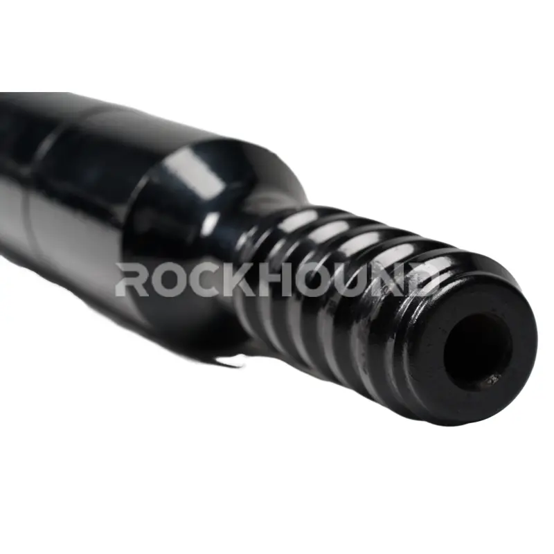
1. Premature Wear of the Tapered Connection
The Problem
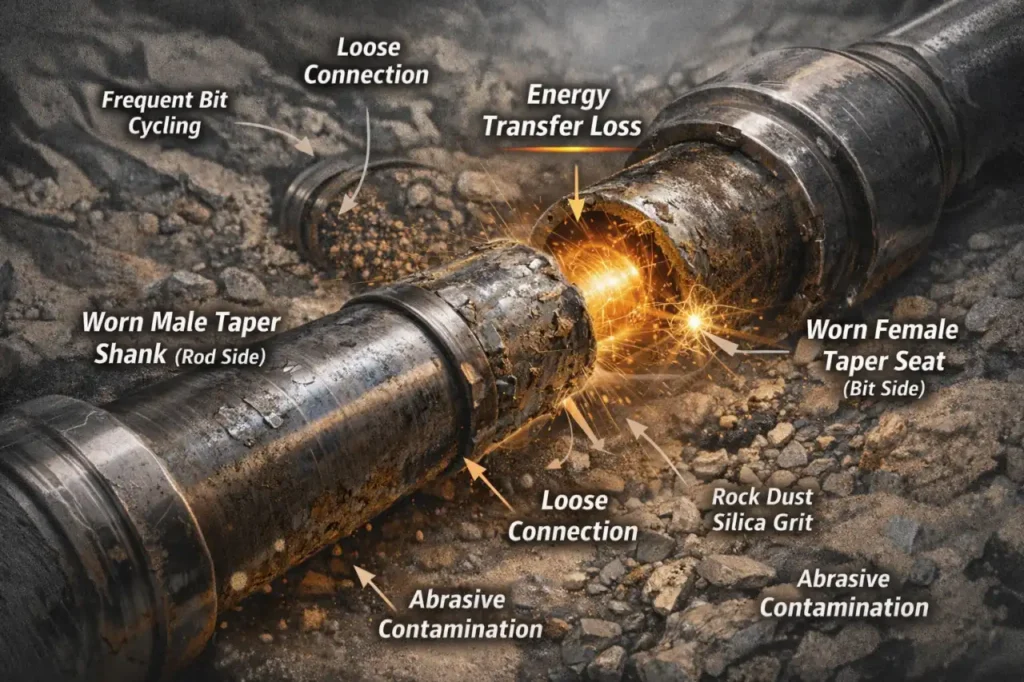
Excessive wear on the male taper shank (rod side) or female taper seat (bit side) is the most frequently reported failure mode in tapered drilling systems. As the mating surfaces degrade, the interface fit loosens, producing a condition engineers refer to as Energy Transfer Loss — the percussive pulse from the rock drill is reflected back rather than transmitted forward into the rock face.
The result is a compounding cycle: loose connection → increased impact vibration → accelerated surface wear → further loosening.
Professional Terminology: Taper Galling, Interface Friction, Energy Transfer Loss, Contact Stress Degradation.
Root Causes
- Taper Angle Mismatch: Using a 7° bit on an 11° or 12° taper rod (or vice versa) creates line contact rather than full surface contact, concentrating stress at discrete points and triggering fretting wear almost immediately.
- Abrasive Contamination: Rock dust, silica fines, or grit trapped inside the taper socket function as a three-body abrasive paste, rapidly scoring the hardened surfaces with every impact cycle.
- High-Frequency Bit Cycling: Frequent removal and re-installation — particularly when performed without the correct extraction tools — damages surface integrity and introduces microscopic scoring.
- Inadequate Heat Treatment: Rods manufactured without controlled high-frequency induction hardening on the taper end lack the surface hardness required to resist fretting fatigue.
RockHound Solutions
- Taper Standardization: Before every shift, verify that the taper angle designation — 7°, 11°, or 12° — is identical on both the rod and the bit. Never assume interchangeability between different taper series. When in doubt, use a taper gauge.
- The “Clean-First” Protocol: Wipe both the male shank and the female socket with a clean, dry cloth before each assembly. Even a thin layer of abrasive dust can reduce connection life by 30–50%.
- Specify Surface-Hardened Rods: Source drill rods that specify high-frequency induction hardening on the taper zone, targeting a minimum surface hardness of 58–62 HRC.
- Monitor Contact Pattern: When a rod is new, check the contact pattern using engineer’s blue (Prussian blue). Full-surface contact across ≥70% of the taper length indicates a well-matched pair.
RockHound Note: Our tapered drill rods are manufactured from 23CrNi3Mo alloy steel(Conpare With Sanbar 64) with a controlled carburization and induction hardening process, delivering the surface hardness and toughness required to resist taper wear in high-abrasion hard rock environments.
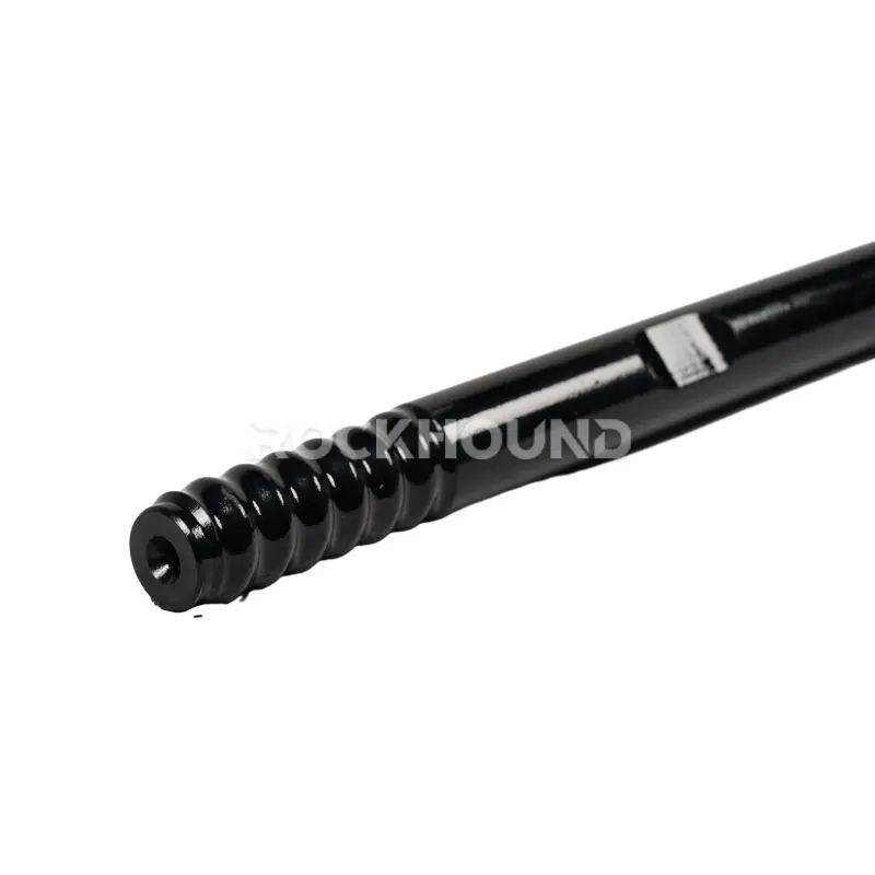
2. Drill Rod Bending and Axial Deviation
The Problem
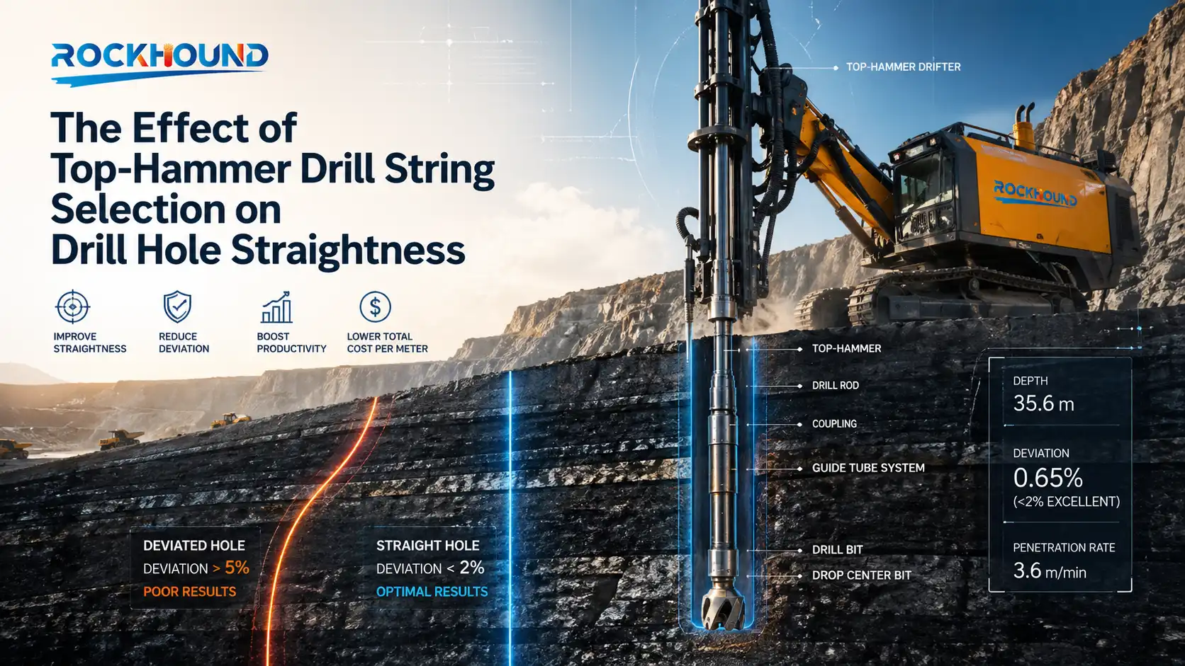
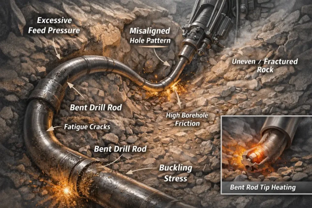
A drill rod that loses its geometric straightness creates a cascade of operational problems: crooked blast holes that misalign with the drill pattern, increased borehole wall friction that overheats the rod and bit, and ultimately fatigue failure caused by the cyclically reversing bending stresses imposed on a deflected shaft under rotation and impact.
Even a bend as small as 2–3 mm over a 1,200 mm rod length can reduce service life by more than 50% in hard rock applications.
Professional Terminology: Axial Deviation, Lateral Buckling, Buckling Stress, Hole Straightness, Bending Fatigue.
Root Causes
- Excessive Feed Pressure (Over-feeding): Applying feed force beyond the drill’s specified thrust rating causes the rod to laterally buckle (“snake”) inside the hole, particularly in the early meters of collaring.
- Collaring Errors: Initiating the hole on an uneven, fractured, or inclined rock face without reducing impact power allows the rod tip to deflect before the bit is stabilized.
- Incorrect Rod Length Selection: Drilling with a long rod (e.g., 2,400 mm) from the surface — rather than commencing with a starter rod (guide steel) of 600–800 mm — leaves the rod unsupported over an excessive free length, greatly increasing the risk of buckling.
- Fractured or Anisotropic Rock Formations: Drilling through voids, clay seams, or highly fractured rock can cause sudden lateral loading that deflects the rod.
RockHound Solutions
- Calibrated Feed Force (Matched Feeding): Adjust the rock drill’s feed pressure to match measured rock compressive strength. As a rule of thumb, feed force should not exceed 50–60% of the drill’s nominal thrust when collaring. Increase progressively once the bit is fully stabilized.
- Mandatory Starter Rod Protocol: Always begin each hole with a shorter guide steel or starter rod (typically 600 mm) to establish correct angular alignment and protect the full-length rod from first-meter deflection.
- Pre-shift Straightness Inspection: Roll all rods on a flat surface (a steel plate or concrete floor works well). Any rod that exhibits a visible “wobble” — indicating a bow of >1 mm/m — should be removed from service immediately. Straightening bent rods cold introduces residual stress and is not recommended; reheating destroys the heat treatment.
- Correct Rod Selection for Depth: Match rod length to hole depth. For holes under 1.5 m, use a dedicated short drill steel. For progressive deeper holes, start short and extend.
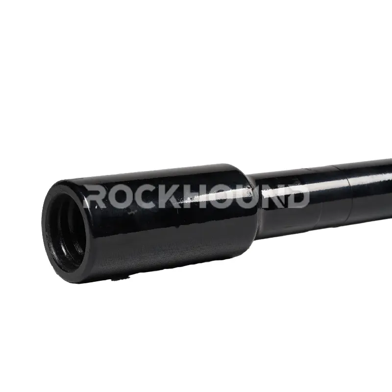
3. Drill Bit Loosening and Taper Slippage
The Problem
The tapered connection relies on an interference fit — the bit is driven onto the rod taper until friction between the mating surfaces is sufficient to transmit both torque and axial retraction force. When this interference is insufficient, the bit rotates freely on the rod during the retraction (pull-back) stroke, or detaches entirely, leaving a Lost-in-Hole (LIH) situation that requires expensive fishing operations or hole abandonment.
Professional Terminology: Taper Slippage, Interference Fit Failure, Secondary Impact, Lost-in-Hole (LIH).
Root Causes
- Insufficient Pre-seating Force: Simply pushing the bit onto the taper by hand does not generate the required interference. Without an initial seating blow, the friction coefficient is too low to resist retraction forces.
Polished or Worn Taper Surfaces: Surfaces that have undergone significant wear develop a low-roughness “mirror” finish, drastically reducing the coefficient of static friction and the available retraction force.
- Contamination in the Taper Bore: Dust, water, or oil film in the taper socket acts as a lubricant, reducing the interference fit force.
- Thermal Expansion Effects: In deep or hot-rock drilling, asymmetric thermal expansion between the rod shank and the bit body can relax the interference fit during operation.
RockHound Solutions
- Mandatory Pre-seating Blow: Before starting the drill, give the bit a firm, single strike using a copper or brass mallet — never steel-on-steel, which risks spalling the hardened surfaces. The goal is to produce a light interference deformation that locks the taper under the initial impact cycles.
- Surface Condition Inspection: Inspect taper surfaces for polishing, scoring, or corrosion before each assembly. A lightly textured, rust-free surface provides optimal friction coefficient. Replace any rod or bit exhibiting a polished contact zone.
- Taper Bore Cleaning: Remove all debris and moisture from the female taper socket before bit installation. Compressed air is ideal; avoid lubricants on the taper interface.
- Thermal Compensation in Hot-Rock Applications: In geothermal or deep hard rock environments where rock temperatures exceed 60°C, seat the bit with additional force and verify tightness after the first 30–50 cm of drilling.
4. Fatigue Breakage — Shank and Mid-Body Fracture
The Problem
The tapered connection relies on an interference fit — the bit is driven onto the rod taper until friction between the mating surfaces is sufficient to transmit both torque and axial retraction force. When this interference is insufficient, the bit rotates freely on the rod during the retraction (pull-back) stroke, or detaches entirely, leaving a Lost-in-Hole (LIH) situation that requires expensive fishing operations or hole abandonment.
Professional Terminology: Taper Slippage, Interference Fit Failure, Secondary Impact, Lost-in-Hole (LIH).
Root Causes
- Insufficient Pre-seating Force: Simply pushing the bit onto the taper by hand does not generate the required interference. Without an initial seating blow, the friction coefficient is too low to resist retraction forces.
- Polished or Worn Taper Surfaces: Surfaces that have undergone significant wear develop a low-roughness “mirror” finish, drastically reducing the coefficient of static friction and the available retraction force.
- Contamination in the Taper Bore: Dust, water, or oil film in the taper socket acts as a lubricant, reducing the interference fit force.
- Thermal Expansion Effects: In deep or hot-rock drilling, asymmetric thermal expansion between the rod shank and the bit body can relax the interference fit during operation.
RockHound Solutions
- Zero-Tolerance Blank Firing Policy: Train operators to never engage the drill hammer without confirmed bit-rock contact. In mechanized drilling, use feed pressure interlocks where available.
- Anti-Corrosion Storage and Handling: After each shift, clean rods and apply a thin film of rust-inhibiting oil (SAE 30 or equivalent). Store in a dry, ventilated environment on proper rod racks — never directly on damp ground. Discard any rod with visible pitting.
- Specify Premium Alloy Steel: Specify drill rods manufactured from 23CrNi3Mo, 25CrMo, or equivalent high-grade alloy steels — materials with a proven track record of high fatigue strength and toughness under percussive loading. Demand mill certificates where possible.
- Visual Fatigue Inspection Protocol: Before each shift, inspect rods under good lighting for hairline cracks radiating from the shank fillet or from any surface irregularity. A 10× magnifying loupe is a worthwhile investment. Any rod showing surface cracks must be retired immediately.
RockHound Note: All RockHound tapered drill rods are manufactured from 23CrNi3Mo alloy steel and undergo a full carburization → quenching → tempering heat treatment cycle, verified by hardness testing on each production batch, to deliver the fatigue life demanded by high-intensity percussive drilling.
[Related Reading:Taper Drill Rod Manufacturing Process]
5. Reduced Penetration Rate (Low Drilling Efficiency)
The Problem
When a drill rig is running but Penetration Rate (PR) has dropped significantly from baseline, and the rock type has not changed, a mechanical cause should be suspected before attributing the problem to formation hardness. Low PR directly increases cost-per-meter and often signals a developing tool problem that will lead to more serious failure if not addressed.
Professional Terminology: Penetration Rate (PR), Flushing Efficiency, Energy Attenuation, Bit Wear Flat, Specific Energy (SE).
Root Causes
- Clogged Flushing Channel: The central water or air flushing bore of the rod or bit is blocked by accumulated rock cuttings or mineral precipitation. Without effective hole flushing, the bit is re-crushing its own cuttings — a condition that can reduce PR by 40–60% and dramatically increase bit wear.
- Excessive Bit Wear (Dull Carbide): When the wear flat on tungsten carbide inserts exceeds one-third (1/3) of the button diameter, the contact area between the bit and rock has increased to the point where the available drill energy is insufficient to maintain rock fracture, and PR collapses.
- Loose Taper Connection (Energy Attenuation): As described in Section 1, a worn taper connection attenuates the percussive pulse. The Specific Energy (SE) required to break rock is higher, and PR falls accordingly.
- Incorrect Rod Length: Excessively long rods introduce additional elastic energy storage, reducing the peak force delivered to the bit face.
RockHound Solutions
- Flushing System Verification: At the start of each shift, verify that the rock drill’s flushing tube is intact and delivering adequate air or water pressure (target: ≥ 4 bar for air flushing; ≥ 2 bar for water flushing). Check the bit’s flushing ports are clear; use a wire probe if necessary.
- Bit Wear Monitoring and Grinding Schedule: Measure wear flat diameter with calipers. Regrind or replace tungsten carbide inserts when the wear flat exceeds 1/3 of the nominal button diameter. In hard, abrasive rock, establish a routine grinding interval based on drilled meters rather than waiting for visible PR decline.
- Taper Connection Integrity Check: Confirm that the rod-bit connection is tight. A loose taper is frequently misdiagnosed as “hard rock” when it is actually a tool problem.
- Match Rod Length to Application: For shallow holes (< 2 m), always use the shortest appropriate rod to minimize elastic losses.
Best Practices for Tapered Drill Rod Maintenance
Effective maintenance is the single highest-return investment in tapered drilling tool management. Implementing the following field protocols consistently will reduce consumable spend, extend tool life, and improve drilling efficiency.
Pre-Shift Inspection Checklist:
- Visually inspect all rods for hairline cracks, severe pitting, and geometric deformation (roll test)
- Check taper surfaces for wear, polishing, or contamination
- Verify flushing bore is clear (blow through with compressed air)
- Confirm rod-bit taper angle match before assembly
During Drilling:
- Never blank-fire the drill hammer
- Apply feed force calibrated to rock type — do not over-feed
- Always collar with a starter rod on fresh rock faces
- Monitor PR; any unexplained drop warrants immediate inspection
Post-Shift Handling:
- Clean all tapered surfaces and apply rust-inhibiting oil
- Store rods horizontally on padded racks in a dry environment
- Log drilled meters per rod to track service life and predict replacement cycles
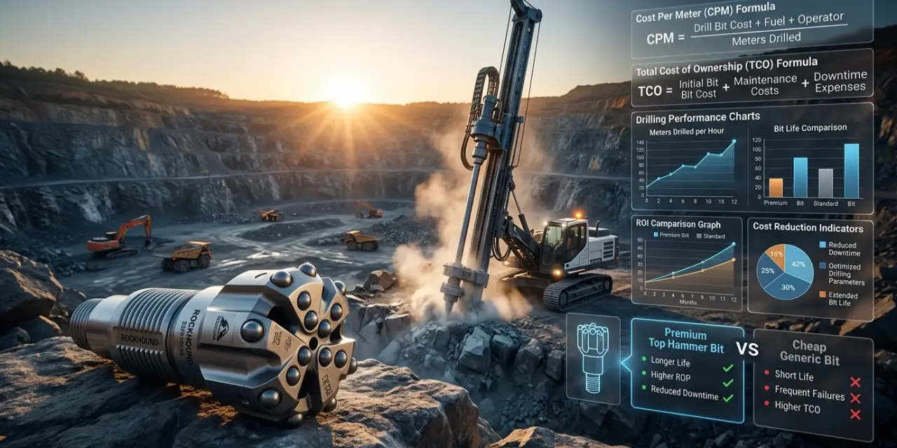
Why Drill Tool Material Quality Determines Total Cost of Ownership
In percussive drilling, the total cost of ownership (TCO) of a drill rod is not its purchase price — it is the cost per meter drilled over its service life. Premium alloy steel rods manufactured with controlled heat treatment may carry a 20–30% higher unit price than generic alternatives, but they consistently deliver 2–4× longer service life, fewer in-hole failures, and lower labor costs from reduced bit changes and rod recoveries.
Key material indicators to specify when sourcing tapered drill rods:
- Steel Grade: 23CrNi3Mo, 55SiMnMo, or declared equivalent with mill certificate
- Surface Hardness (Taper Zone): 58–62 HRC minimum
- Core Toughness: Charpy impact value ≥ 40 J at ambient temperature
- Heat Treatment: Full carburization + quench + temper cycle, verified by batch testing
- Straightness Tolerance: ≤ 1 mm/m over full rod length
About RockHound
RockHound specializes in the design and manufacture of high-performance rock drilling tools for mining, quarrying, construction blasting, and tunneling applications. Our product range includes:
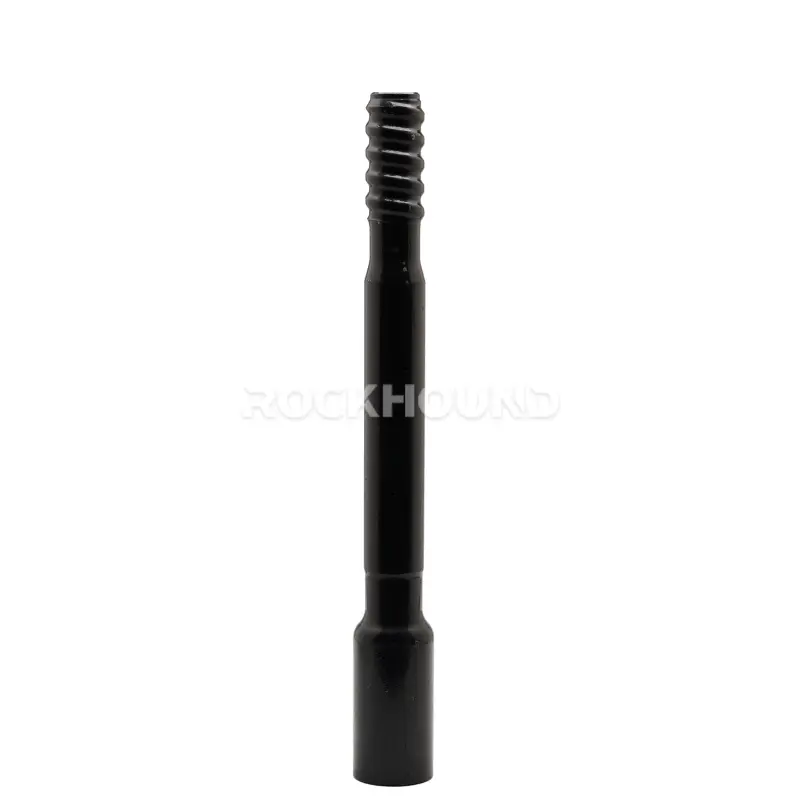
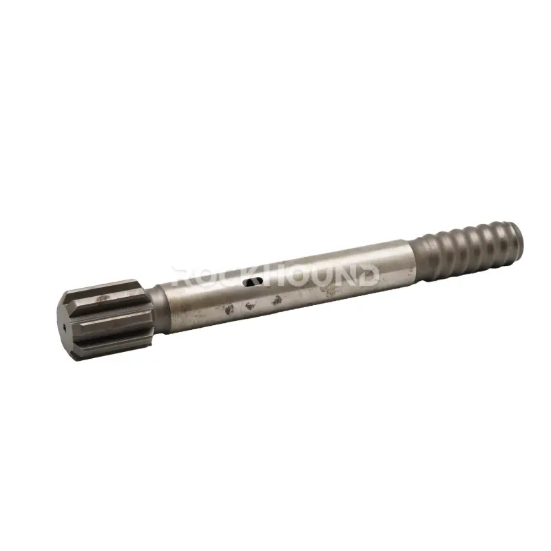
- Tapered Drill Rods — 7°, 11°, and 12° taper series
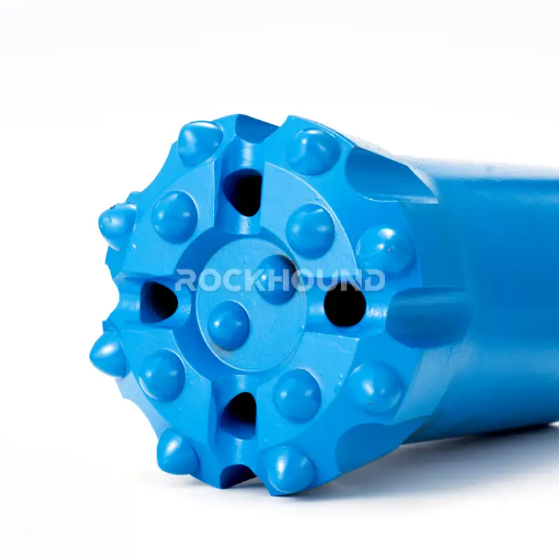
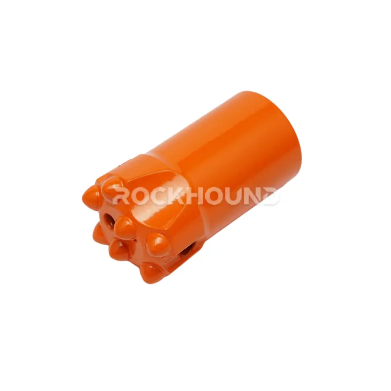
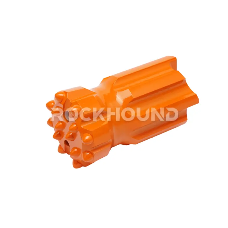
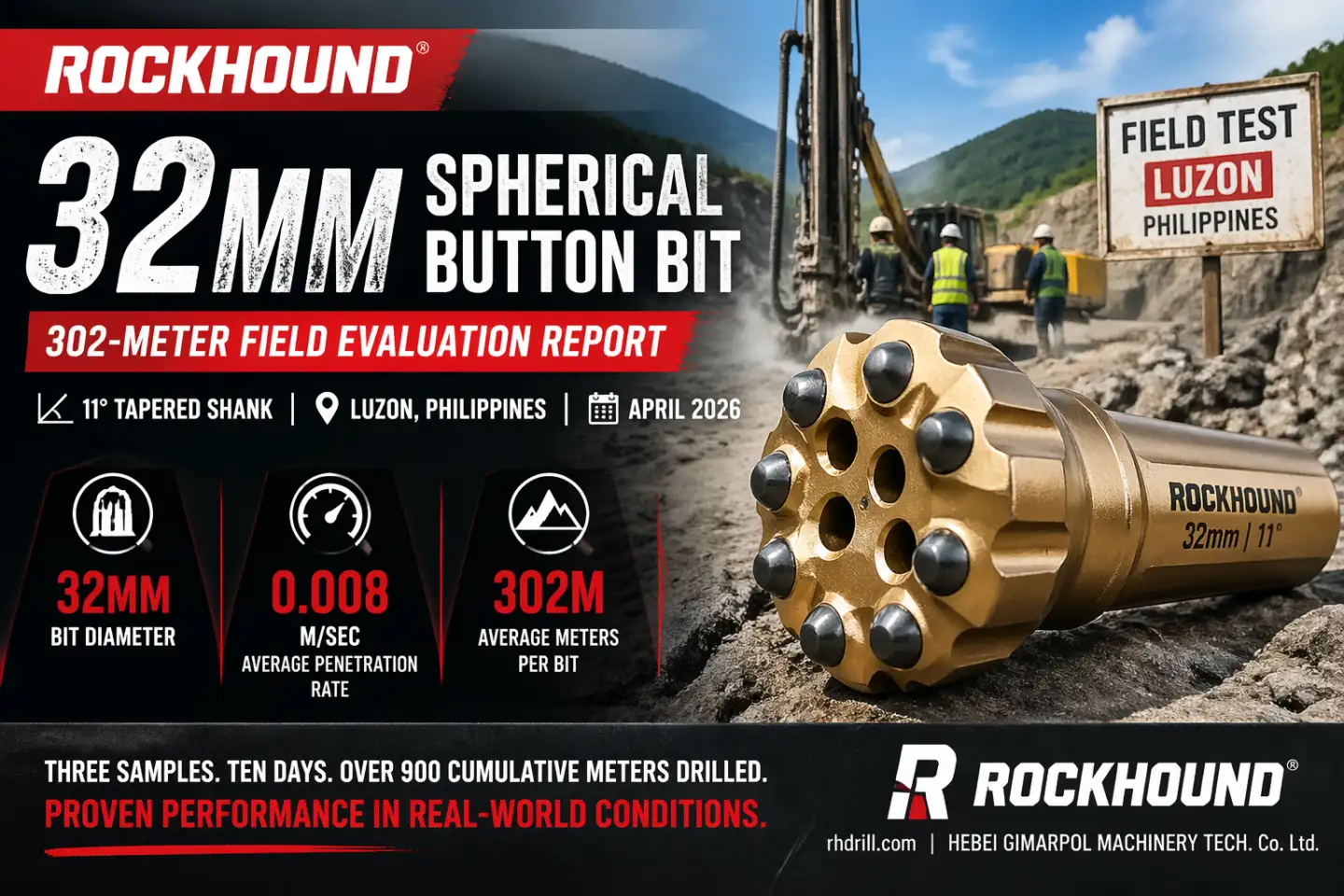
- Tapered Drill Bits — Ballistic and spherical carbide button configurations
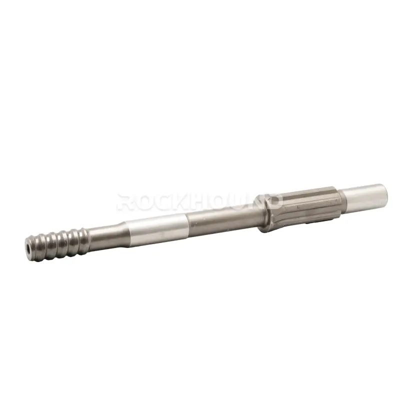
- Integral Drill Steels — For compact, high-efficiency hand-held drilling
All RockHound products are manufactured from premium alloy steel with documented heat treatment and quality control inspection, engineered to deliver consistent performance and extended service life in demanding drilling environments.
FAQ
Taper angle selection is governed by rock drill model and application severity. 7° tapers are associated with lighter hand-held drills and softer rock formations, where the lower interference angle is sufficient for the retraction forces involved. 11° and 12° tapers are specified for heavy-duty percussive drills operating in hard, abrasive formations — the steeper angle generates higher interference force and a more secure bit retention under high-impact loading. Always consult your drill manufacturer's specification sheet and match the rod and bit to the same taper series.
No. Cold straightening introduces plastic deformation that creates residual tensile stress on the outer fiber — the exact location where fatigue cracks initiate. Hot straightening above the tempering temperature destroys the heat treatment, reducing both hardness and fatigue strength. A bent rod must be removed from service and replaced. The cost of rod replacement is negligible compared to the cost of an in-hole fracture.
The grinding interval depends on rock abrasivity and formation hardness. As a standard guideline, inspect the wear flat at regular intervals (every 20–30 m drilled in hard rock). Regrind when the wear flat reaches one-third (1/3) of the button diameter. Maintaining sharp carbide inserts dramatically reduces specific energy consumption and extends bit life.
Blank firing (also called dry firing) means operating the drill hammer with the bit not in contact with the rock. In normal drilling, the rock face absorbs a large proportion of each impact pulse. Without that energy sink, the full stress wave is reflected back along the rod, generating stress amplitudes up to 40% higher than normal operating loads. Even brief intervals of blank firing can initiate fatigue cracks that propagate to failure within a single shift.