Table of Contents
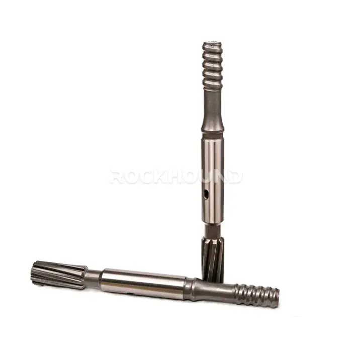
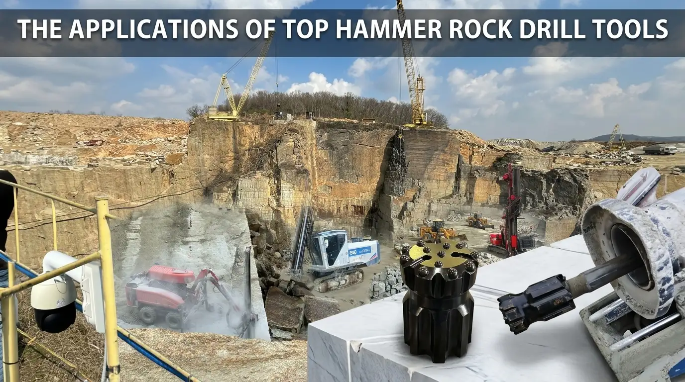
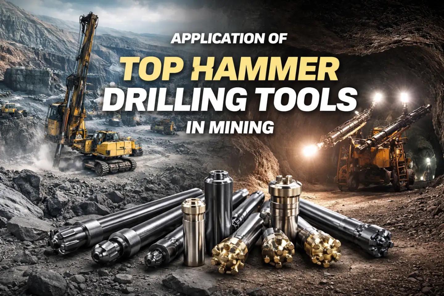
In top hammer drilling — whether surface bench blasting, underground development, or tunneling — drill rod is the primary conduit for percussive energy between the rock drill and the drill bit. Selecting the wrong rod type does not simply mean slower penetration rates; it means accelerated thread wear, premature rod fatigue, poor hole straightness, and inflated consumable costs.
Two rod configurations dominate the market: the Speed MF Rod (Male/Female Drill Rod) and the Extension Drill Rod (Ext Rod). Both are manufactured to the same material and heat treatment standard. Their functional differences, however, are significant — and understanding them is the foundation of any rational drill string selection process.
What They Share: The Quality Foundation
Before examining where these two rod types diverge, it is important to establish the baseline: a properly manufactured Speed MF Rod and Extension Drill Rod are built to an identical material and processing specification. Any performance difference between them is a function of design, not raw material grade.
Raw Material — 23CrNiMo High-Alloy Steel
Both rod types are produced from 23CrNiMo, a chromium-nickel-molybdenum low-alloy case-hardening steel widely regarded as the industry-standard material for percussive rock drilling tools. Its alloy composition delivers a critical combination of properties that generic carbon steels cannot replicate:
- High fatigue resistance — withstands millions of percussive stress cycles without crack initiation
- Superior impact toughness — absorbs transient shock loads in hard and fractured rock without brittle fracture
- Strong wear resistance — maintains thread geometry and rod body integrity under continuous abrasive loading
- Hardenability depth — the Cr-Ni-Mo alloy system enables deep, uniform case hardening that plain carbon steel cannot achieve
The choice between 23CrNiMo and alternative grades such as Sandvik’s Sanbar 64 involves trade-offs in through-hardness vs. case depth. For a full metallurgical comparison, see: Rock Drill Rod Material Comparison: 23CrNiMo vs Sanbar64
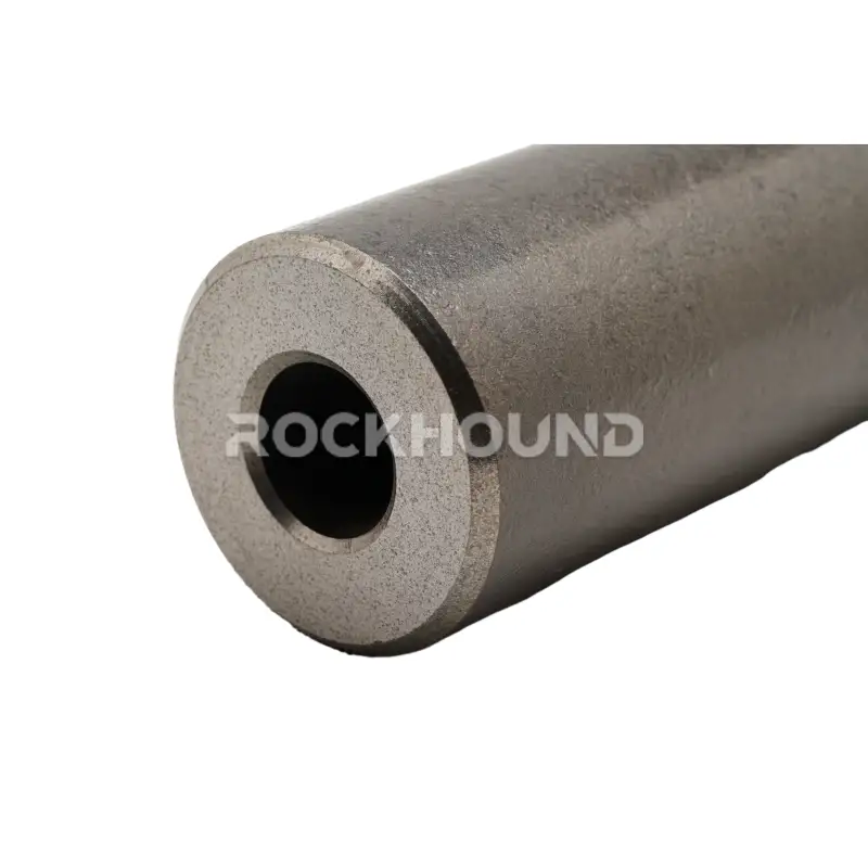
Manufacturing Process — Center Hole Extraction
Both rod types undergo the center hole extraction process, in which the central flushing channel is bored axially from the geometric center of the raw steel billet — rather than from offset tooling. This precision process is a non-negotiable quality requirement for professional-grade drilling rods for three reasons:


- Uniform wall thickness — eliminates thin-wall zones that create stress concentration points and premature fatigue cracks
- Concentric geometry — ensures the rod rotates on its true axis, reducing bending moments during drilling and improving hole straightness
- Consistent flushing flow — a centered bore maintains predictable hydraulic resistance for water and air flushing throughout the rod string
Related reading:
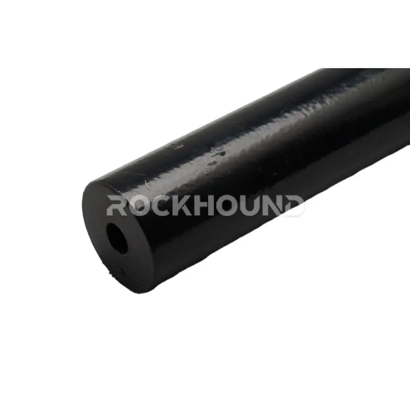
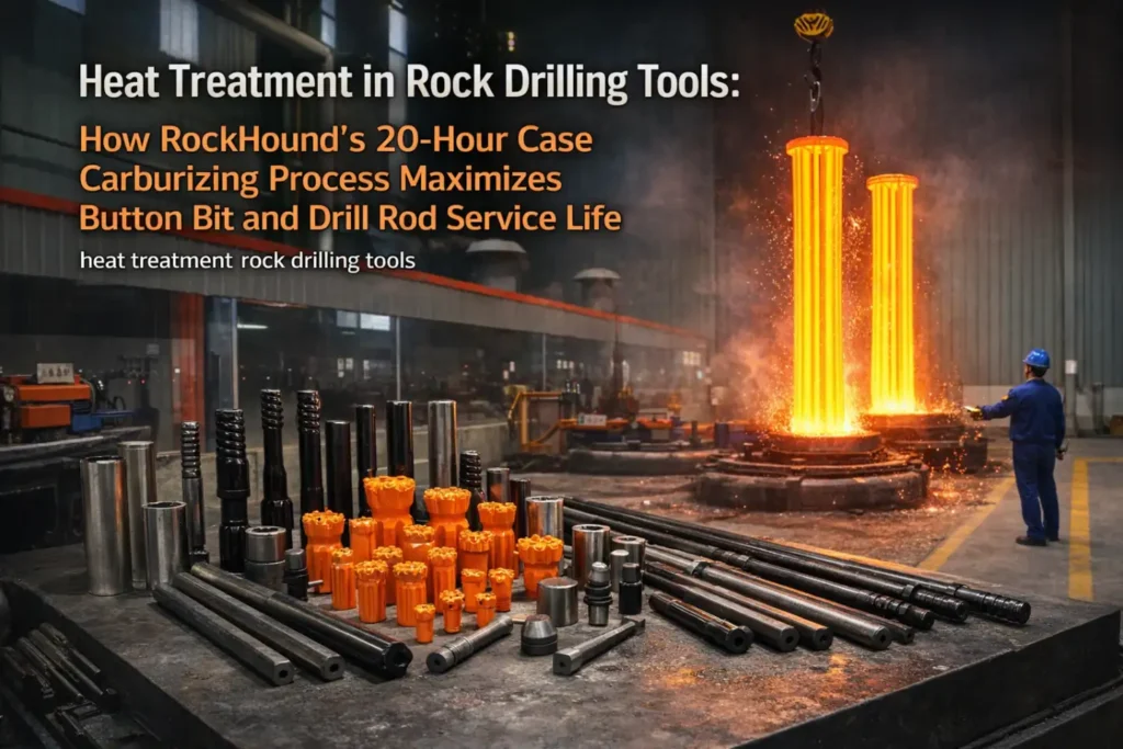
Heat Treatment — 20-Hour Deep Carburization
Both rod types undergo a 20-hour deep carburizing cycle — substantially longer than the 8–12-hour cycles common in budget manufacturing. This extended cycle is not arbitrary; it is the minimum required to achieve a case depth and hardness profile that meets the demands of heavy-duty top hammer applications:
- Case hardness HRC 58–62 at the rod surface and thread flanks — resists thread deformation and abrasive wear from formation particles entrained in the flushing flow
- Case depth of 1.5–2.5 mm — provides sufficient wear allowance over the full service life of the rod
- Tough, ductile core (HRC 35–42) — absorbs percussive impulse energy without crack propagation from the case into the core
- Compressive residual stress layer — induced by the carburization and quench cycle, this surface stress state actively resists fatigue crack initiation
Rods produced with shorter carburization cycles present a characteristic failure mode: thread flanks deform under load before the rod body approaches end-of-life, forcing premature replacement and inflating per-meter costs.
Reference: 20-Hour Heat Treatment in Rock Drilling Tools
Key Takeaway: The Speed MF Rod and the Extension Drill Rod are manufactured from the same alloy, processed by the same method, and hardened to the same specification. Material quality does not differentiate them — connection geometry does.
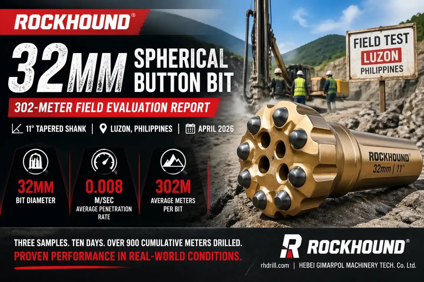
Project Test Report:
Key Differences: A Technical Comparison
| Feature | Speed MF Rod (Male/Female) | Extension Drill Rod (Male/Male) |
|---|---|---|
| Thread Configuration | One male (pin) end + one integrated female (box) end | Two male (pin) ends — symmetric profile |
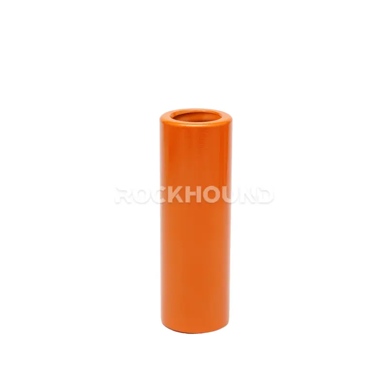
| Connection Method | Direct rod-to-rod — no coupling sleeve required | Requires a separate coupling sleeve at every joint |
| Stress Wave Transmission | Higher efficiency — integrated joint minimises impedance mismatch and reflective energy loss | Slight energy loss at each coupling junction due to mass discontinuity |
| Hole Straightness | Superior — lower angular compliance at each joint; preferred for deep, precision holes | Standard — minor angular play at coupling sleeve; adequate for shallow-to-medium depths |
| Annular Flushing Clearance | Greater — slim female end leaves more annular space for cuttings evacuation | Reduced — coupling OD exceeds rod body OD; can restrict flushing in tight borehole diameters |
| Wear & Replacement Logic | Female (box) end is the primary wear point; when worn, entire rod is retired | Coupling sleeve is the primary wear component; replaced independently — rod bodies continue in service |
| Rod Change Cycle Time | Faster — single rotational engagement per joint; compatible with automated rod carousels | Longer — coupling sleeve management adds steps per rod change; suited to manual operations |
| Inventory Complexity | Single SKU (rod only) | Two SKUs required (rods + coupling sleeves); coupling sizes must match rod thread profile |
| Typical Application | Automated hydraulic drill rigs · Deep bench drilling · Long-hole stoping · High-accuracy requirements | Manual / semi-automatic rigs · Medium and shallow drilling · Cost-sensitive operations |
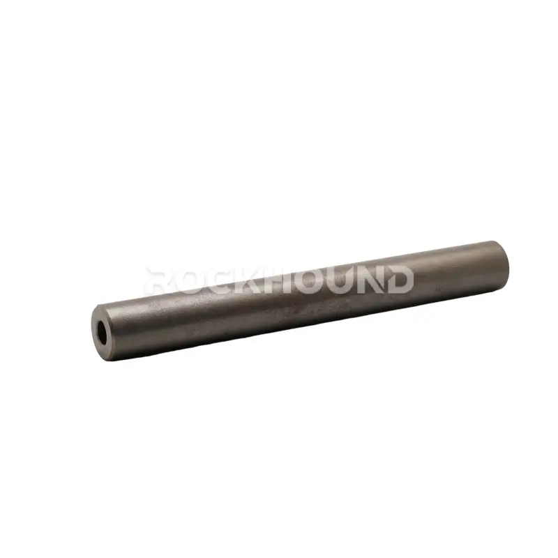
Structural Geometry: The Root Cause of All Differences
The Speed MF Rod integrates the female (box) thread directly into one end of the rod body as a forged-and-machined component. When assembling the drill string, the male (pin) end of the next rod engages directly into this female end. No intermediate component is involved. The joint is a two-body interface.
The Extension Drill Rod carries male (pin) threads at both ends. Joining two rods requires threading a separate coupling sleeve onto one rod’s pin end and then engaging the second rod’s pin from the opposite side. The joint becomes a three-body interface: Rod A pin — Coupling — Rod B pin. This difference in joint architecture is the single origin point for all of the performance distinctions described in this guide.
Stress Wave Transmission Efficiency
In top hammer drilling, the rock drill piston generates a compressive stress wave that travels down the drill string as a one-dimensional elastic wave. The wave’s objective is to deliver maximum specific energy to the drill bit–rock interface. Each joint in the string represents a cross-sectional area change and a mass discontinuity — both conditions that partially reflect the incoming stress wave back toward the drill, reducing net energy delivery to the bit.
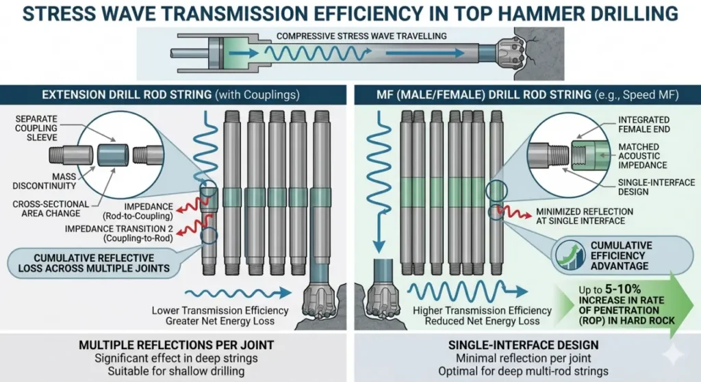
The Speed MF Rod’s integrated female end is machined to match the rod body’s acoustic impedance as closely as possible. The joint still introduces some reflection, but the single-interface design minimises it. Across a four-to-six rod string, this efficiency advantage is cumulative and measurable in penetration rate.
The Extension Drill Rod introduces a coupling sleeve — a separate mass element — at each joint. Because the coupling’s cross-sectional geometry differs from the rod body, the stress wave encounters two impedance transitions per joint (rod-to-coupling and coupling-to-rod), increasing total reflective loss. In shallow drilling (1–3 rods), the effect is negligible. In deep multi-rod strings, it becomes operationally significant.
Summary: MF Drill Rods feature a “built-in” coupling. By eliminating one threaded joint (the separate sleeve), there is less energy loss as the shock wave travels through the drill string. This often results in a 5-10% increase in the Rate of Penetration (ROP) in hard rock formations.
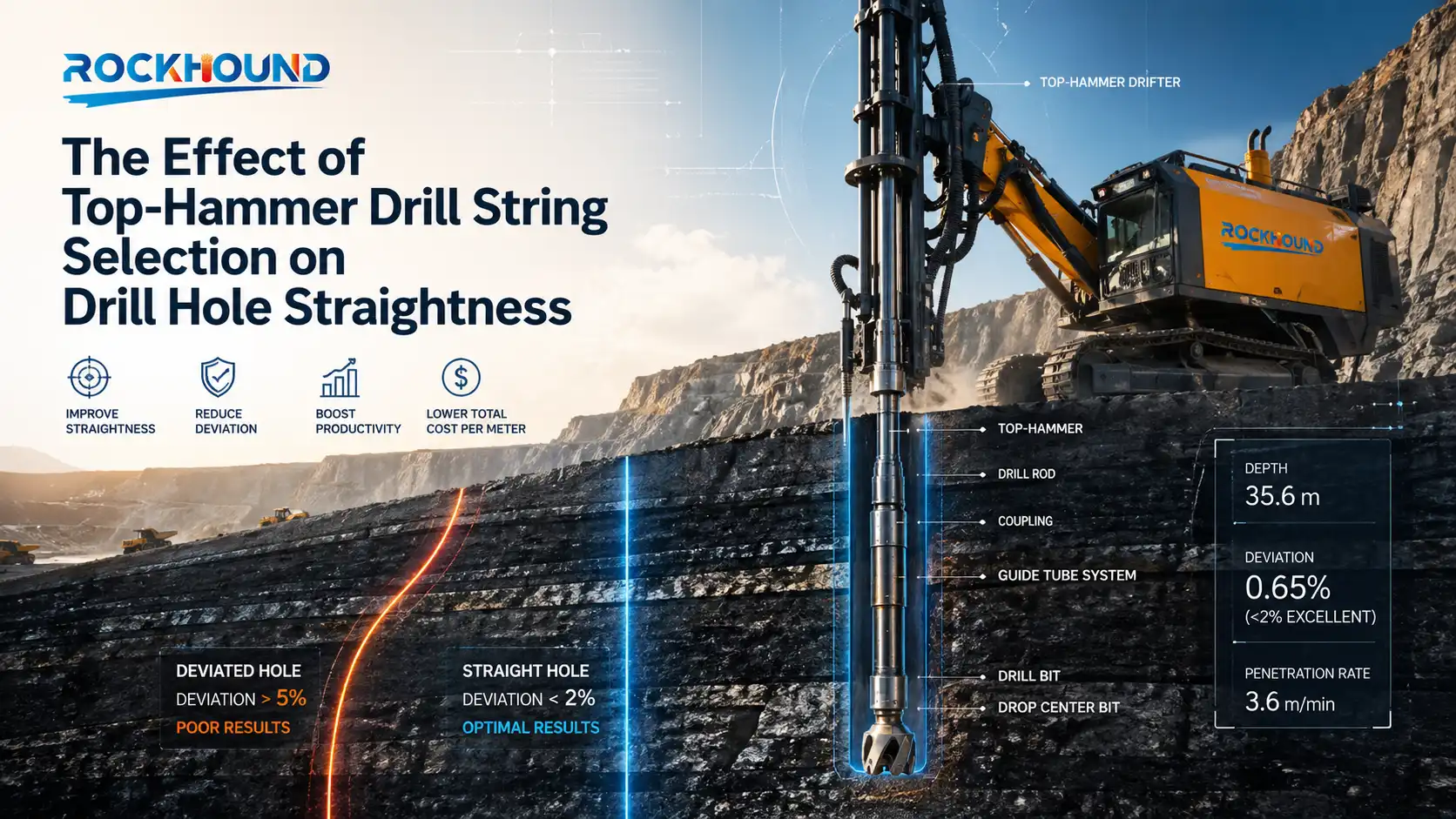
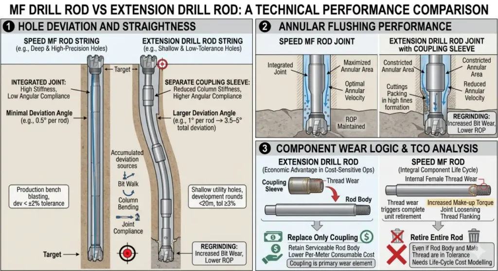
Hole Deviation and Straightness
Hole deviation in rotary-percussive drilling accumulates from three sources: bit walk, rod column bending under feed force, and angular compliance at each rod joint. The Speed MF Rod’s integrated joint provides the highest stiffness and lowest angular compliance of any top hammer rod connection — a direct consequence of eliminating the coupling sleeve as a separate mechanical element.
In production bench blasting, a deviation of 1° per rod length in a 5-rod string produces 3.5–5° total deviation — enough to measurably affect blast fragmentation, sub-drilling efficiency, and powder factor. For applications where hole deviation exceeds ±2% of hole depth tolerance, the Speed MF Rod is the specification-compliant choice.
For shallow utility holes, development rounds under 20 m, or applications where deviation tolerance is ≥3%, the extension rod’s standard straightness is adequate and the cost advantages of coupling replaceability become the dominant selection criterion.
Summary: The integrated female box of an MF rod is machined with high concentricity. For deep-hole benching (over 15m), MF rods significantly reduce hole deviation, ensuring better fragmentation and safer blasting.
Annular Flushing Performance
Efficient removal of drill cuttings from the borehole bottom is critical for maintaining penetration rate. Re-drilling already-broken rock — known as regrinding — accounts for a significant but often unquantified fraction of bit wear and reduced penetration rate. Flushing efficiency is governed by annular velocity, which is a function of the annular area between the rod OD and the borehole wall.
Because the Speed MF Rod’s female end is machined into the rod body profile, its outer diameter at the joint is generally equal to or only slightly larger than the rod body. Annular clearance is maximised.
The coupling sleeve on an extension rod string necessarily has a larger OD than the rod body — it must encompass the male thread of both rods. In borehole diameters close to the coupling OD, this constriction reduces annular flushing velocity and can cause intermittent cuttings packing behind the coupling in formations with high fines generation (weak rock, clay-bearing strata).
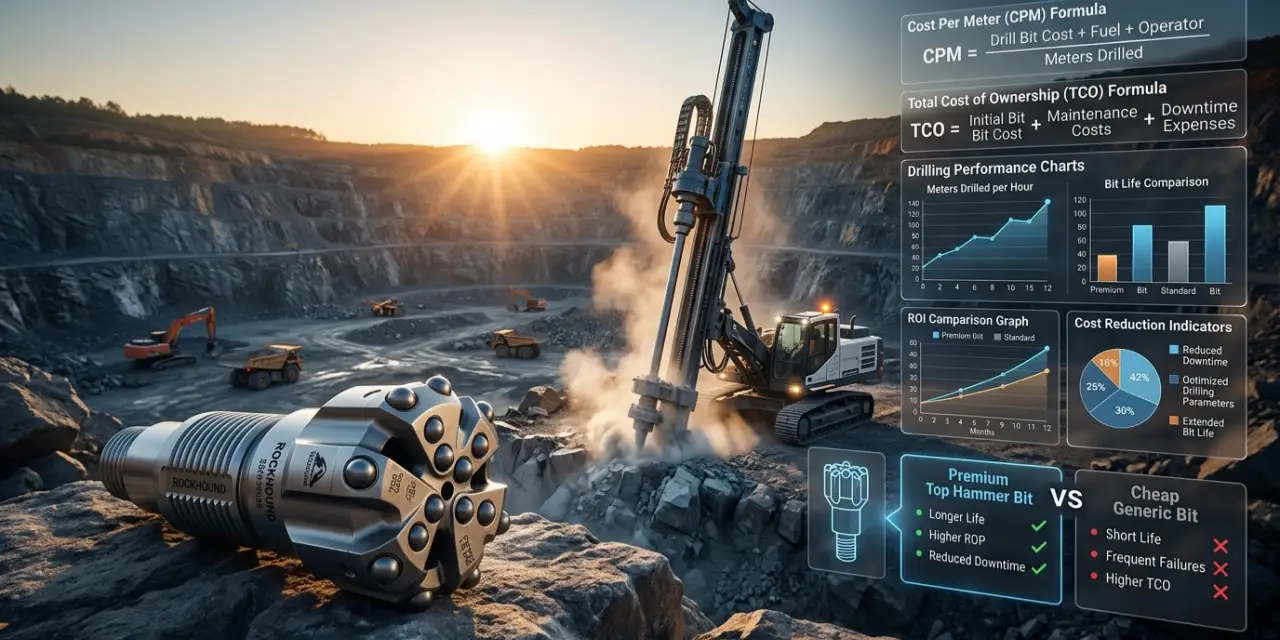
Component Wear Logic and Total Cost of Ownership
This is the area where the Extension Drill Rod holds a clear economic advantage in cost-sensitive operations. The coupling sleeve — not the rod body — is the primary wear element at each joint. Thread wear at the pin-to-coupling interface occurs faster than rod body wear because the coupling is a smaller, lighter component exposed to identical stress concentrations. Replacing only the coupling when worn, while retaining the serviceable rod body, reduces per-metre consumable cost.
On the Speed MF Rod, the female end is integral to the rod. When its internal thread geometry wears beyond specification — typically evidenced by increased make-up torque, joint loosening under rotation, or visible thread flanking — the entire rod is retired, even if the rod body and male thread are still within tolerance. For high-volume operations, this replacement logic needs to be factored into life-cycle cost modelling.
Application Selection Guide
Choose Speed MF Rod When:
- You operate automated hydraulic drill rigs with rod carousel systems (e.g., Sandvik DT/DL series, Epiroc Boomer/Simba)
- Hole straightness is a primary specification — production bench blasting, raise boring, long-hole stoping >20 m depth
- You want to simplify procurement by eliminating coupling sleeves as a separate managed SKU
- Maximising penetration rate is the priority over per-component replacement cost
- Your operation requires fast rod-change cycles to maximise drill utilisation percentage
Choose Extension Drill Rod When:
- Consumable cost control is a dominant KPI — coupling replaceability reduces total cost per metre drilled in medium/shallow applications
- Drilling medium or shallow holes (typically <20 m) where deviation tolerance is standard
- Your equipment is a manual or semi-automatic rig where coupling management is a standard part of the operator’s workflow
- You operate multiple drill rigs on variable specifications and prefer coupling-based flexibility in matching rods to different thread profiles
- Your organisation maintains high inventory of rod bodies and wants to maximise asset utilisation through coupling replacement
Summary
| Parameter | Speed MF Rod | Extension Drill Rod |
|---|---|---|
| Primary Strength | Efficiency + precision + automation compatibility | Cost flexibility + component replaceability |
| Key Trade-off | Higher unit replacement cost when female end wears | Added coupling SKU management; slight energy loss at joints |
| Ideal Application | Automated rigs, deep holes, high-accuracy blasting | Manual rigs, medium/shallow holes, budget-sensitive ops |
| Material / Heat Treatment | 23CrNiMo · 20-hr carburization | 23CrNiMo · 20-hr carburization |
RockHound Recommendation: The decision between Speed MF Rod and Extension Drill Rod is an application engineering decision, not a quality decision. Match the connection geometry to your rig type, target depth, and cost structure. Both perform to specification when manufactured correctly — the difference is in how they perform for your specific operation.
Get a Custom Drill Rod Specification from RockHound
Not sure which rod fits your project? Tell us your:
- Drill rig model
- Target rock type and UCS (MPa)
- Hole depth and borehole diameter
RockHound’s engineering team will provide a free drill string specification matched to your exact operating conditions.
Frequently Asked Questions
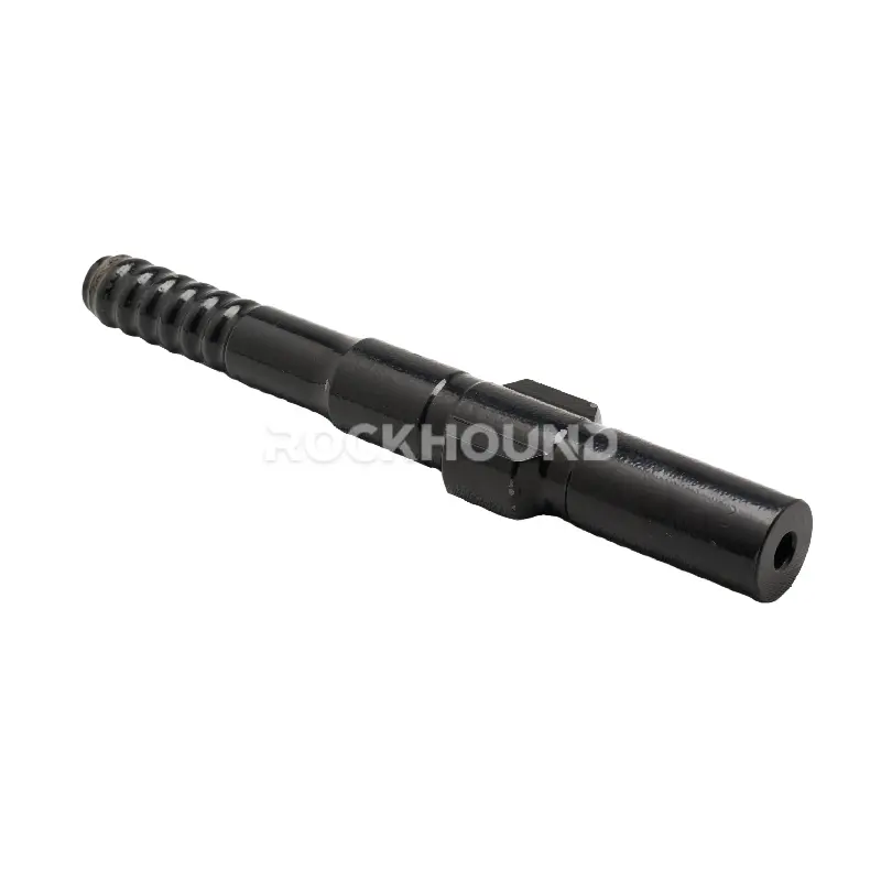
The Speed MF Rod (Male/Female Drill Rod) features one male (pin) thread at the shank end and one integrated female (box) thread at the other. It is called "Speed" because the direct rod-to-rod connection — requiring no coupling sleeve — significantly reduces rod-change cycle time compared to extension rod configurations. This design is particularly advantageous on automated hydraulic drill rigs with rod carousel systems, where each second saved per rod change compounds across a full production shift.
No. Speed MF Rods and Extension Drill Rods use fundamentally incompatible connection geometries and cannot be combined in a single drill string. An MF rod's female end is designed to receive another rod's male end directly; an extension rod's male-male configuration requires a coupling sleeve to join to any other rod. Attempting to mix these types would result in either no mechanical engagement or incorrect thread mating, risking joint failure under percussive loading.
Ensure your entire drill string uses a consistent rod type matched to the shank adapter and drill bit thread specification.
All else being equal, the Speed MF Rod delivers marginally better penetration rates in hard rock deep-hole applications. The integrated joint reduces stress wave reflection losses at each rod connection compared to the coupling sleeve interface of an extension rod. In a single-rod or two-rod string, this difference is negligible. In a five-to-six rod string (20–30 m holes), the cumulative energy efficiency difference becomes measurable — typically 3–7% higher net energy delivery to the bit face, depending on rock mechanical properties and drill operating parameters.
Note that bit selection, feed force optimisation, and flushing efficiency generally have a larger influence on ROP than rod type selection.
Coupling sleeve service life varies significantly with rock type, drilling depth, rotation speed, and flushing medium. As a general field guideline, coupling sleeves typically require replacement at 30–50% of the rod body's service life in hard abrasive rock (e.g., granite, quartzite), and at 50–70% of rod body life in medium-hardness rock.
Inspect couplings regularly for: (1) visible thread flank deformation or galling, (2) increased make-up torque requirements, (3) joint loosening during rotation. Replace couplings at the first sign of these indicators — continuing to use a worn coupling accelerates wear on the rod pin threads and can cause catastrophic joint separation downhole.
23CrNiMo is the most widely used material for top hammer drill rods and represents the industry standard for professional-grade tools. It provides an excellent balance of case hardenability, core toughness, and fatigue resistance for the majority of drilling applications.
Alternative proprietary steel grades — such as Sandvik's Sanbar 64 — are used in OEM tools and are engineered for specific performance characteristics, such as higher through-hardness or modified alloy ratios for extremely abrasive formations. However, 23CrNiMo manufactured with proper process controls (centre hole extraction + 20-hour carburization) consistently meets or exceeds the performance benchmarks of comparable applications.
Related reading: Material Comparison: 23CrNiMo vs Sanbar64
Carburization depth is a function of time at temperature. A 20-hour carburizing cycle at the appropriate temperature achieves a case depth of approximately 1.5–2.5 mm in 23CrNiMo steel. Shorter cycles (8–12 hours, common in budget manufacturing) produce shallower case depths of 0.6–1.2 mm.
In service, the drill rod threads experience severe combined loading: axial tension and compression from the percussive stress wave, torsion from rotation, and bending from hole deviation. Thread flanks are subjected to Hertzian contact stress at each make-up engagement. A shallow case layer is worn through quickly, exposing the softer core material — leading to accelerated thread deformation and premature rod failure. The 20-hour cycle is not a marketing specification; it is a minimum engineering requirement for professional service life.
Reference: Full Heat Treatment Technical Guide
Thread profile selection is determined by your drill rig's shank adapter specification and the target borehole diameter. As a general reference:
- R32 — 33–51 mm borehole diameter; light to medium duty top hammer applications
- R38 — 38–57 mm; standard medium-duty surface and underground drilling
- T38 — 38–57 mm; higher torque capacity than R38 due to coarser thread pitch; preferred in harder rock
- T45 — 45–64 mm; heavy-duty underground and surface bench drilling
- T51 — 51–76 mm; large-diameter heavy-duty applications, high-energy rock drills
Always verify thread compatibility between shank adapter, rod, coupling (for extension rods), and drill bit. Mismatched threads cause immediate joint damage and void product warranty.
Field service life is primarily driven by four operational practices:
- Thread lubrication — apply rod grease to all threaded connections before each make-up. Dry threads generate galling and fretting fatigue within hours of operation
- Correct make-up torque — over-tight connections pre-stress the thread flanks and cause fatigue cracking; under-tight connections allow fretting wear and joint loosening. Follow the drill manufacturer's specified torque values
- Rotate rod position in the string — the rod nearest the shank adapter experiences the highest stress amplitude. Rotating rods through string positions distributes wear evenly across the inventory
- Inspect and retire at the right threshold — worn threads on Speed MF Rod female ends and on coupling sleeves should be retired before they cause catastrophic joint failure downhole. Rod recovery from a deep hole after in-hole separation costs far more than a new rod