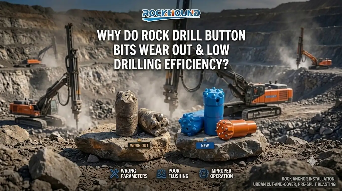
When the Drill Bit Isn't the Problem
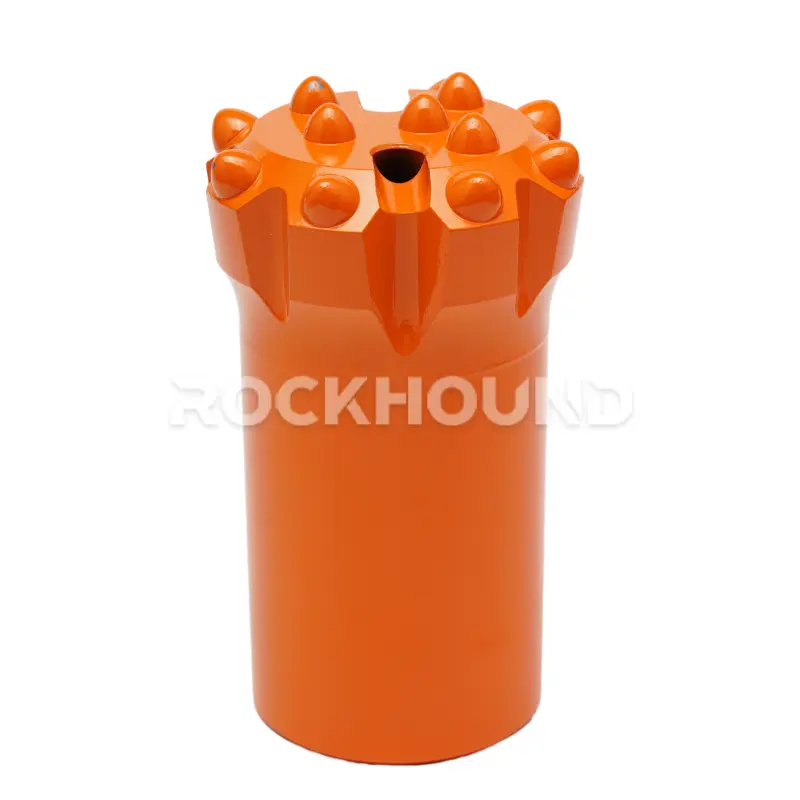
Walk any quarry face or tunnel heading and you’ll hear the same complaint: rock drill button bits are burning through too fast. The reflexive response is to point at the supplier. But a properly manufactured button bit, which forged from 45CrNiMoVa steel, carburized for 20 hours, and pressed with YK05 carbide inserts, which is built to endure tens of thousands of percussive blows per minute across demanding formations.
When one fails early, the first question should never be “what’s wrong with this tool?” It should be: “what is happening on that drill rig?”
Forensic analysis of worn bits pulled from job sites in granite quarrying, pre-split blasting, and urban foundation drilling consistently tells the same story. Accelerated wear and low penetration rates trace back to operating habits — not metallurgy. That matters because operating habits are fixable the same day.

The Applications Where This Hurts Most
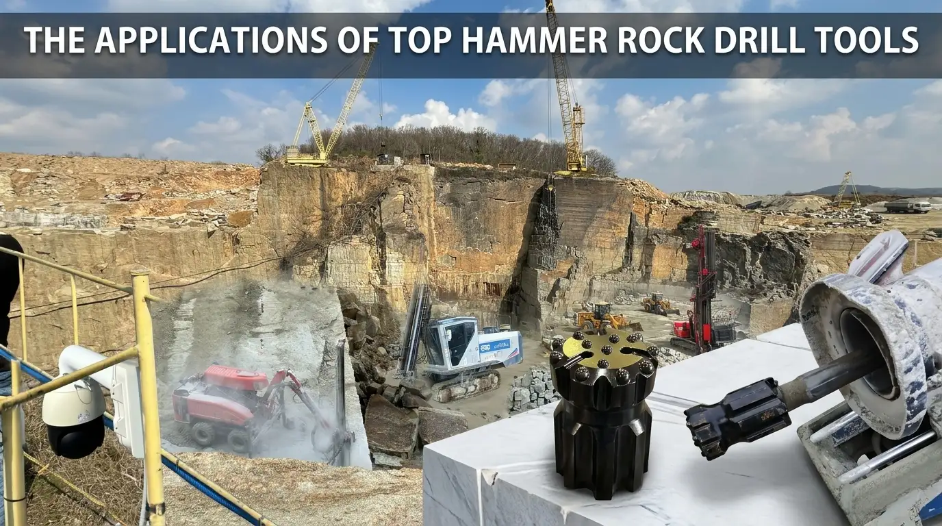
Top-hammer button bits work across a wide range of geotechnical scenarios, and the loading conditions shift dramatically between them.
Rock anchor installation and anchor hole drilling for slope stabilization or retaining structures force the bit through alternating competent and fractured zones. The drill string absorbs lateral shock as rock transitions between stable and loose material. Feed force that was correct in solid granite becomes excessive in a jointed seam, bending the rod and misaligning the percussive axis.
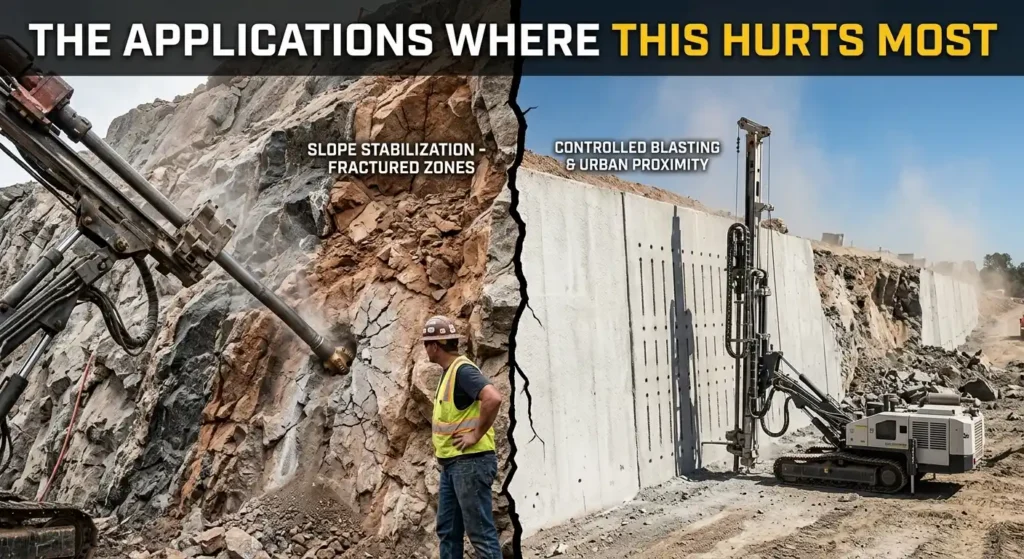
On road cutting projects and pre-split blasting patterns, where the target is a controlled fracture plane at precise spacing. The bit’s gauge condition directly affects final wall quality. A worn bit scatters energy rather than channeling it forward, producing over-break and irregular face profiles. In urban controlled blast environments where municipal vibration limits apply, that reflected energy amplifies ground motion beyond permitted thresholds.
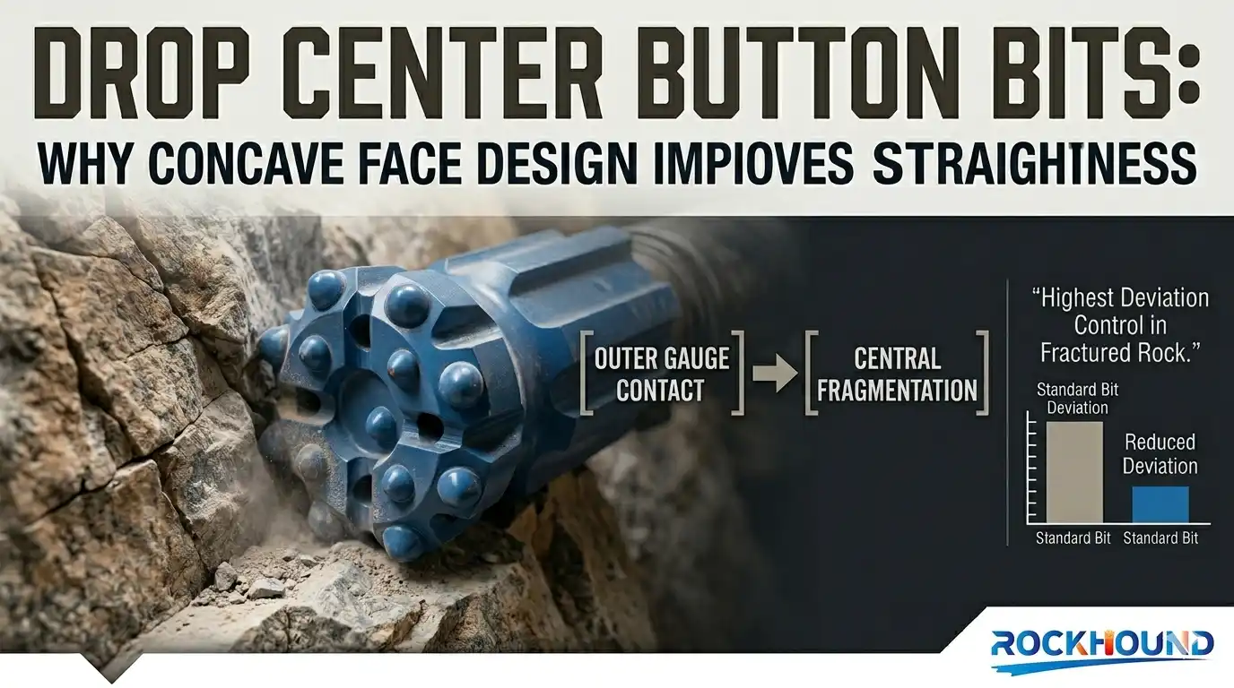
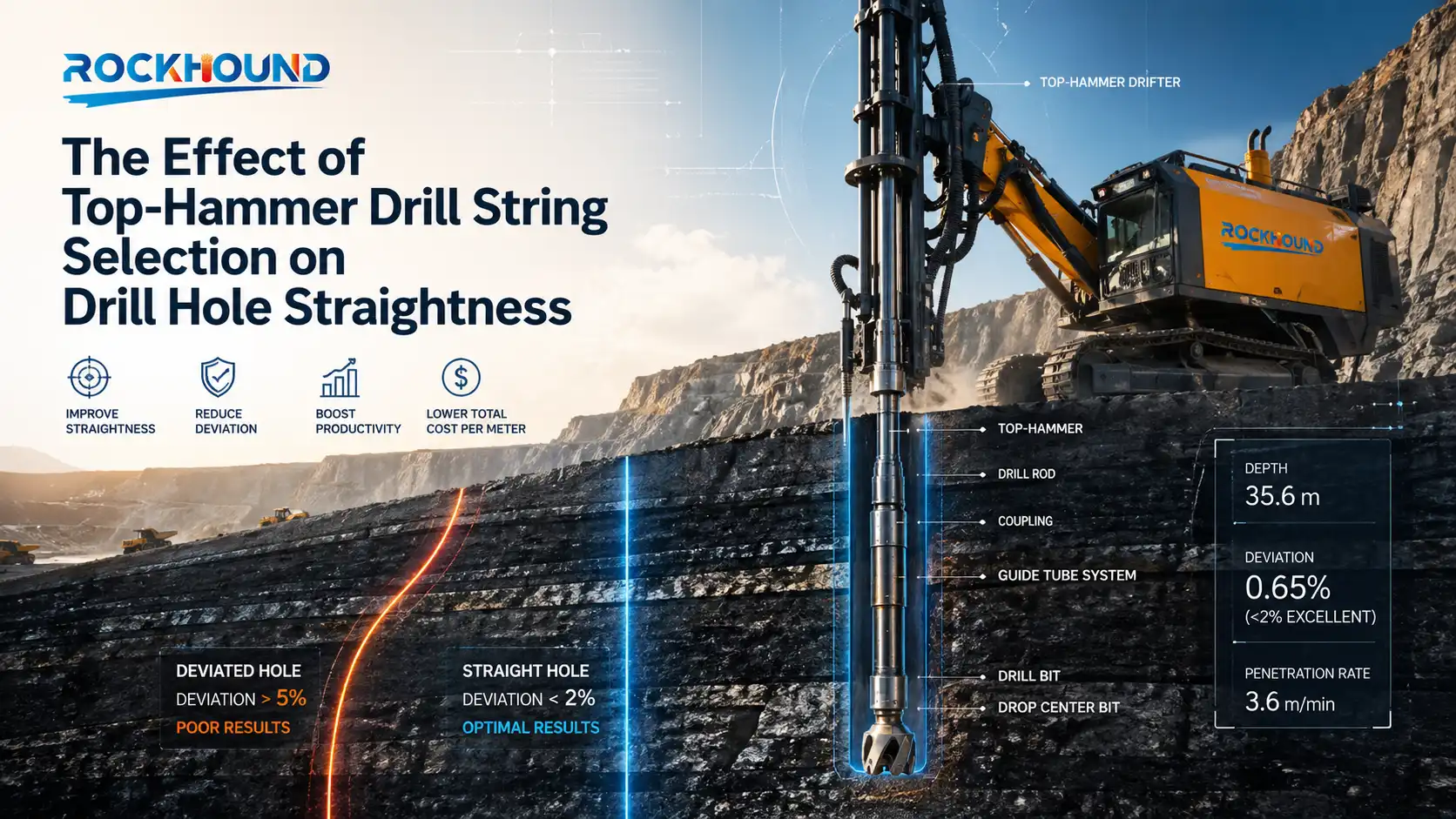
Urban cut-and-cover excavations and foundation drilling in built-up areas add proximity constraints. Hole straightness is mandatory when working meters from live utilities. A bit with an anti-taper wear profile, where gauge diameter has eroded below the rod diameter — doesn’t just penetrate slowly. It deflects. On a cut-and-cover project, that deviation can put a borehole into an adjacent service corridor.
Four Reasons Button Bits Wear Out Fast
Bit degradation is rarely a single-shift event. It compounds over dozens of holes before it becomes visible. It almost always starts with one or more of these four patterns.
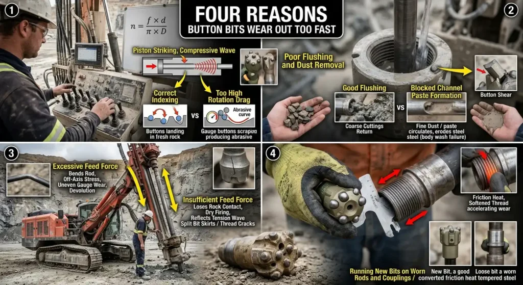
1. Incorrect Impact or Rotation Settings
The top-hammer system works through a defined energy sequence: piston strike → compressive wave through the rod → controlled compressive load on the carbide buttons at the rock face. That sequence depends on rotation speed being matched to percussive frequency.
In hard rock, when rotation speed runs too high relative to impact frequency, the gauge buttons on the outer perimeter drag across the rock surface between blows rather than indexing cleanly onto a fresh contact point. That sliding action is pure abrasion. Over hours, it grinds the carbide gauge flat and reduces the overall bit diameter — a condition called anti-taper wear.
Once anti-taper develops, the bit body contacts the borehole wall on every millimeter of advance. Torque spikes. The rotation motor strains. Penetration rate collapses. If the bit is not pulled and re-ground at this point, the rod will often stall or snap.
A reliable starting point for setting rotation speed is the index spacing formula:
n = (f × d) / (π × D)

Where n = rotation speed (RPM), f = percussive blow frequency (Hz), d = target button indexing distance per blow (1/3 to 1/2 of button diameter), and D = bit diameter (mm). Running this calculation before entering a new formation takes three minutes and prevents hours of lost footage.
For a deeper look at how percussive energy moves through the drill string and reaches the rock face, see: Top Hammer Button Bit: How It Works, Uses & Maintenance
2. Poor Flushing and Dust Removal
When flushing air or water pressure drops — or when a flushing channel partially blocks — freshly cut rock chips do not clear the borehole face. The bit grinds over the same debris on the next blow, and the one after that.
Re-ground particles mix with any moisture present in the hole and become a fine abrasive paste. This paste circulates around the bit head and progressively erodes the steel matrix surrounding the carbide buttons — a failure mode called body wash. As the steel retreats, the buttons protrude beyond their designed depth. Once protrusion exceeds approximately 75% of the button diameter, the remaining steel can no longer anchor the carbide against lateral impact. Buttons shear off at face level.
In underground drifting and tunneling applications, water flushing pressure is typically maintained between 10 and 20 bar to clear heavy cuttings from confined holes at depth. On surface drill rigs working in dry conditions, air velocity at the bit face must be sufficient to carry chip sizes of 8–10 mm back up to the collar.
Field indicator: Watch what comes out of the hole. Coarse chips in steady volume means the bit is breaking fresh rock and the borehole is clearing. A shift toward fine dust with reduced return volume means re-grinding has started — stop, flush the hole clean, and investigate flushing pressure before continuing.
3. Excessive or Insufficient Feed Force
Feed force is where most parameter errors begin, partly because it’s the control operators touch most often.
Too much thrust bends the drill rod. A bent rod misaligns the percussive stress wave, which arrives at the bit face at an off-axis angle. The outer gauge buttons take asymmetric impact loads. They chip unevenly. Hole deviation sets in.
Too little feed force is equally damaging. When the bit loses contact with the rock between blows — sometimes called dry firing or free hammering — the percussive wave hits the bit, finds no resistance, and reflects back up the rod as a tension wave. Drill rods and coupling sleeves are not designed to absorb tension efficiently. Thread joints crack. Bit skirts split. In hard rock operations, a single extended dry-firing event can cause failures that accumulate into a string of broken rods across the remainder of a shift.
Neither failure mode is dramatic in the first hour. By the third or fourth shift under bad feed conditions, the cost in rods, bits, and drill time becomes very apparent.
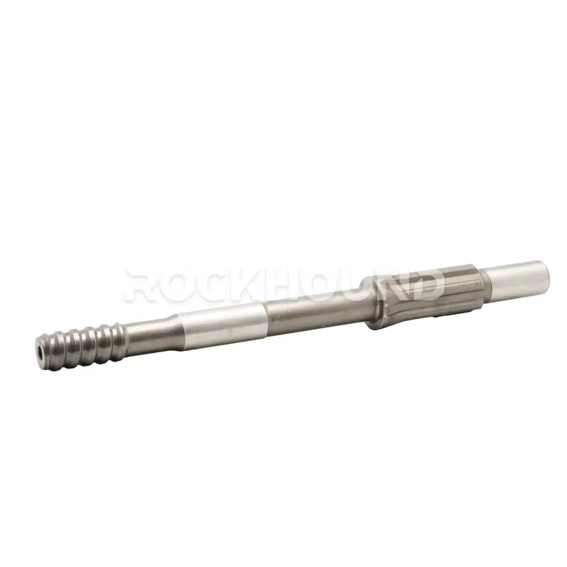
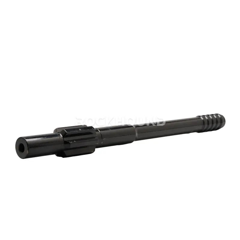
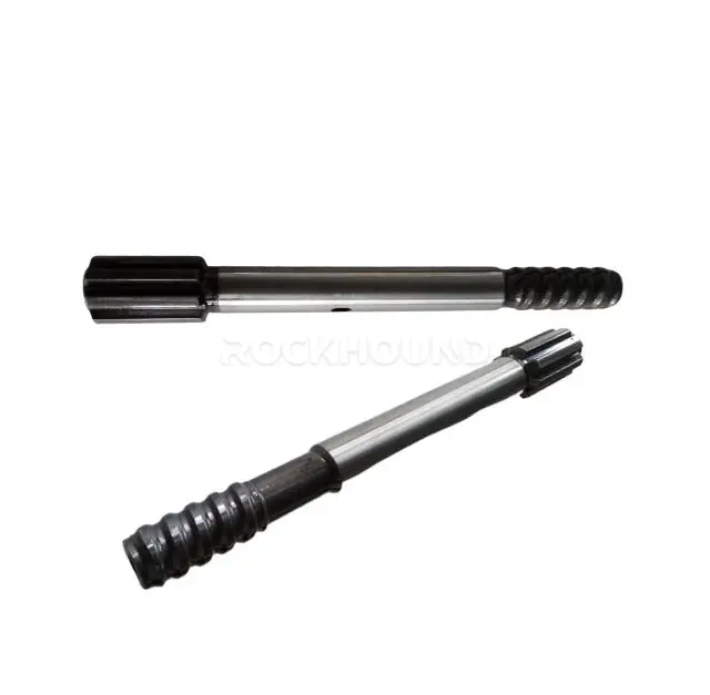
4. Running New Bits on Worn Rods and Couplings
A new button bit installed on a worn coupling sleeve with measurable thread clearance creates a loose connection in the drill string. Every percussive blow produces a small amount of relative movement at that joint.
That joint movement converts impact energy into friction heat rather than transmitting it forward as a coherent stress wave. Transmission efficiency drops. Penetration rate drops with it. The joint temperature rises high enough to temper the steel locally, softening the thread and accelerating wear further. Over a shift, the driller increases percussive pressure to compensate for the drop in penetration — which puts even more load on an already degraded connection.
The field rule is simple: before threading on a new bit, check rod and coupling thread condition. If the wear flat on the thread profile exceeds manufacturer tolerance — typically verified with a thread gauge — rotate the rod out of service. The cost of one worn coupling sleeve exceeds the cost of several replacement bits.
Low Drilling Efficiency? Fix 3 Parameters First
Good equipment producing slow drilling almost always means a parameter mismatch. The bit is usually fine. Here is where to look.
Match Parameters to Rock Hardness
The core framework:
| Rock Type | UCS (MPa) | Feed Force | Rotation Speed | Percussive Pressure |
|---|---|---|---|---|
| Soft (Limestone, Shale) | < 80 | Low | 150–200 RPM | Moderate |
| Medium (Sandstone, Schist) | 80–150 | Moderate | 100–140 RPM | Moderate–High |
| Hard (Granite, Basalt, Quartzite) | 150–250+ | High (5–15 kN) | 80–120 RPM | Maximum |
The non-negotiable rule: do not run high rotation in hard rock. In granite or basalt above 180 MPa UCS, high rotation speed destroys gauge carbide faster than any other single factor. The bit needs to hit hard and index precisely — not spin fast.
For guidance on matching bit face design to specific formations, see: Top Hammer Drill Bit Types: Face Design & Button Shape
The Flushing Protocol That Gets Skipped
Most drillers understand flushing matters. Fewer follow through when the shift is behind schedule. Three habits make the most difference:
Monitor cuttings return continuously. Volume and chip size coming from the hole collar are real-time indicators of borehole health. Coarse chips mean fresh rock is being broken. Fine dust in low volume means re-grinding has started. Catching this early costs five minutes of downtime. Missing it costs a damaged bit and a slow hole.
Stabilize flushing pressure before the shift. On large sites where compressors serve multiple drill rigs simultaneously, pressure fluctuations are common. During low-pressure intervals, chip transport velocity drops and cuttings settle around the bit. Check compressor output and line pressure before drilling begins.
Run a cleaning cycle at every rod addition. When adding extension rods on deep holes, stop percussion before threading and flush the borehole clear. In clay-rich or wet formations, cuttings compact quickly. In dry, hard rock quarrying, abrasive dust packs tight. Neither clears itself once drilling resumes.
| Formation | UCS (MPa) | Recommended Bit | Feed Force | Rotation (RPM) | Primary Wear Risk | Field Response |
|---|---|---|---|---|---|---|
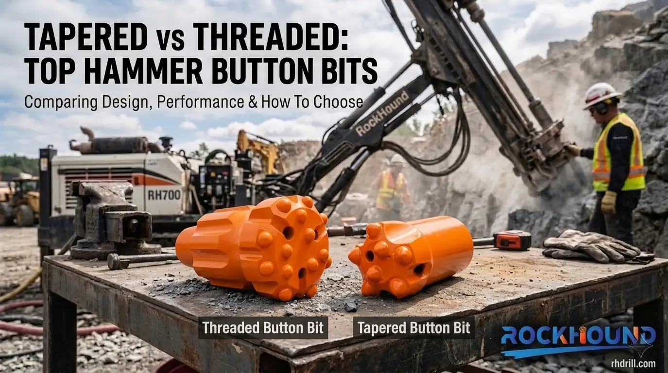
| Granite, Basalt, Gneiss | 150–250 | Spherical buttons, drop-center face | 5–15 kN | 80–120 | Gauge flattening, anti-taper | Re-grind before wear flat exceeds 1/3 of button diameter |
| Quartzite, Siliceous Sandstone | 120–200 | Ballistic buttons, retrac skirt | 8–15 kN | 90–130 | Body wash, button shear | Maintain maximum flushing; inspect button protrusion every 50 m |
| Consolidated Sandstone, Schist | 80–150 | Ballistic buttons, flat face | Moderate | 100–140 | Mixed wear, rod thread fatigue | Balance feed and rotation; inspect rods at each rod change |
| Limestone, Marble | 50–100 | Semi-ballistic buttons, dome face | Low | 140–180 | Minor chipping, flushing channel blockage | Check flushing hole integrity; avoid over-feeding |
| Shale, Claystone | < 50 | Large ballistic buttons, wide flushing grooves | Low | 150–200 | Bit balling, torque spikes | High-volume water flushing; consider chemical drilling fluid additives |
Parameter ranges reflect guidance from Epiroc Rock Drilling Tools Application Guide (2023 ed.) and Atlas Copco Drilling Solutions Technical Reference, cross-referenced against field performance data from HEBEI GIMARPOL production runs in Southeast Asian and South American hard-rock formations.
Material Specification: Where Quality Actually Matters
Once parameters are confirmed and correct, material specification becomes the decisive variable.
Premium top-hammer button bits use 45CrNiMoVa steel for the bit body. The nickel content improves low-temperature impact toughness and slows microcrack initiation under cyclic percussive loading — a meaningful advantage when a hydraulic drifter is delivering 2,000–3,000 blows per minute into granite. After 20-hour deep case carburizing, the hardened surface layer (HRC 58–62 at the case, tapering to a tougher core) provides both abrasion resistance and structural resilience. Standard 42CrMo alternatives, lacking that nickel contribution, erode faster in body-wash conditions and show higher rates of skirt cracking under modern hydraulic drifter outputs.
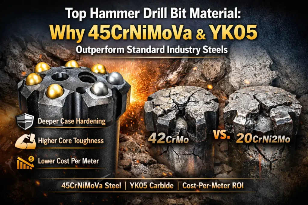
Carbide inserts specified to YK05 grade (94–95% WC, 5–6% cobalt binder) provide the transverse rupture strength needed for hard-rock percussive impact without the brittleness that affects higher-WC grades used in rotary applications.
Full details on how these materials are specified and tested: Top Hammer Drill Bit Material: 45CrNiMoVa & YK05
The manufacturing sequence that turns raw steel and carbide into a finished bit: Rock Drill Bits Manufacturing Process
FAQ
Premature wear on a premium bit is almost always caused by operating conditions rather than the tool itself. The three most common culprits are:
Excessive Rotation Speed: Drags the gauge carbide across the rock face instead of indexing cleanly, causing rapid thermal wear.
Inadequate Flushing: Recirculates abrasive cuttings slurry around the bit head, leading to body erosion.
Worn Drill Rods: Using threads with loose clearances creates energy reflection and severe vibration.
Body wash is the progressive erosion of the steel matrix holding the carbide buttons.
How it starts: Insufficient flushing mixes fine cuttings with drilling fluid, creating an abrasive paste that acts like sandpaper against the steel body.
The consequence: As the steel wears away, buttons lose structural support, protrude too far, and eventually shear off under lateral impacts.
Prevention: Maintain stable flushing pressure and closely monitor cuttings return volume.
In hard formations like granite (> 150 MPa UCS), keep rotation speed between 80 and 120 RPM, paired with high feed force and maximum percussion pressure.
- The Target: Outer gauge buttons should advance 1/3 to 1/2 of their diameter per blow to index onto fresh rock.
- The Formula: Use n = (f · d) / (π · D)
to calculate a practical starting RPM (n). Running above 120 RPM in hard rock accelerates severe anti-taper wear.
Jamming is typically caused by anti-taper wear, where the bit's outer diameter wears down until it is narrower than the bit body, leaving zero borehole clearance.
The Cause: High rotation speeds in hard rock over prolonged periods.
Prevention: Regularly measure the gauge buttons. Pull and regrind the bit before the wear flat reaches ⅓ of the button diameter.
Yes, directly. Loose thread joints between a new bit and worn rods convert percussive energy into destructive friction heat instead of transmitting it into the rock.
To compensate for the lower penetration rate (ROP), operators often mistakenly increase percussive pressure.
This overloads the system, resulting in accelerated button fatigue on the new bit and premature thread failure on the rod. Always inspect rod threads before installing a new bit.
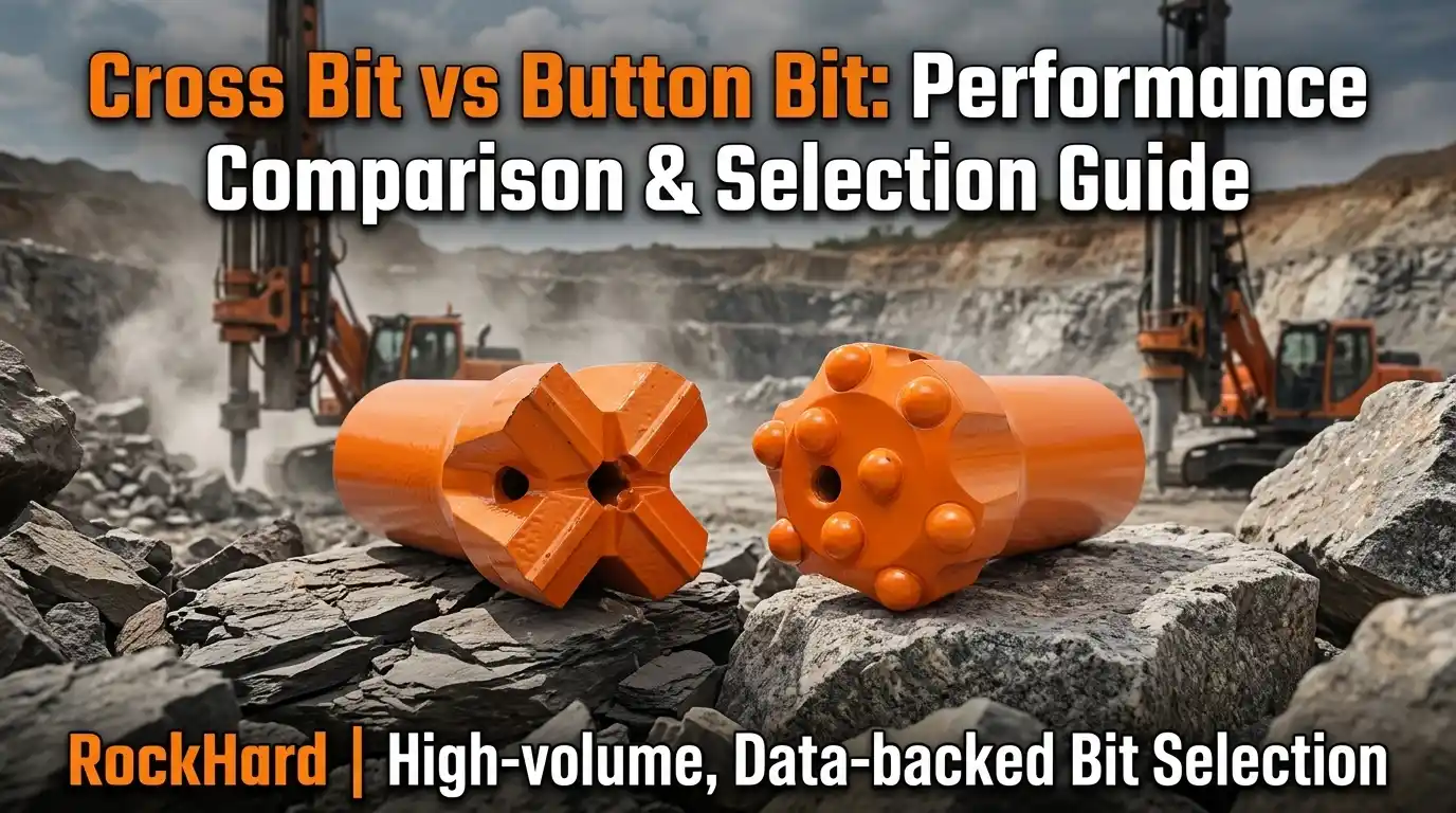
While both applications penalize worn bits severely, their wear profiles and risks differ:
Anchor Hole Drilling: Typically goes through unstable overburden or mixed formations. Shifting lateral loads cause asymmetric gauge wear and risk jamming when transitioning from hard to soft zones.
Pre-split Blasting: Drills through more uniform rock but demands absolute hole straightness. Even minor gauge wear causes hole deviation, which ruins the designed blast geometry and final wall profile.