Table of Contents
In mining, quarrying, construction, and tunneling operations, drilling efficiency is not a technical footnote — it is a direct cost driver. Every meter drilled too slowly, every bit replaced too early, and every rod failure unplanned translates into measurable losses on the bottom line.
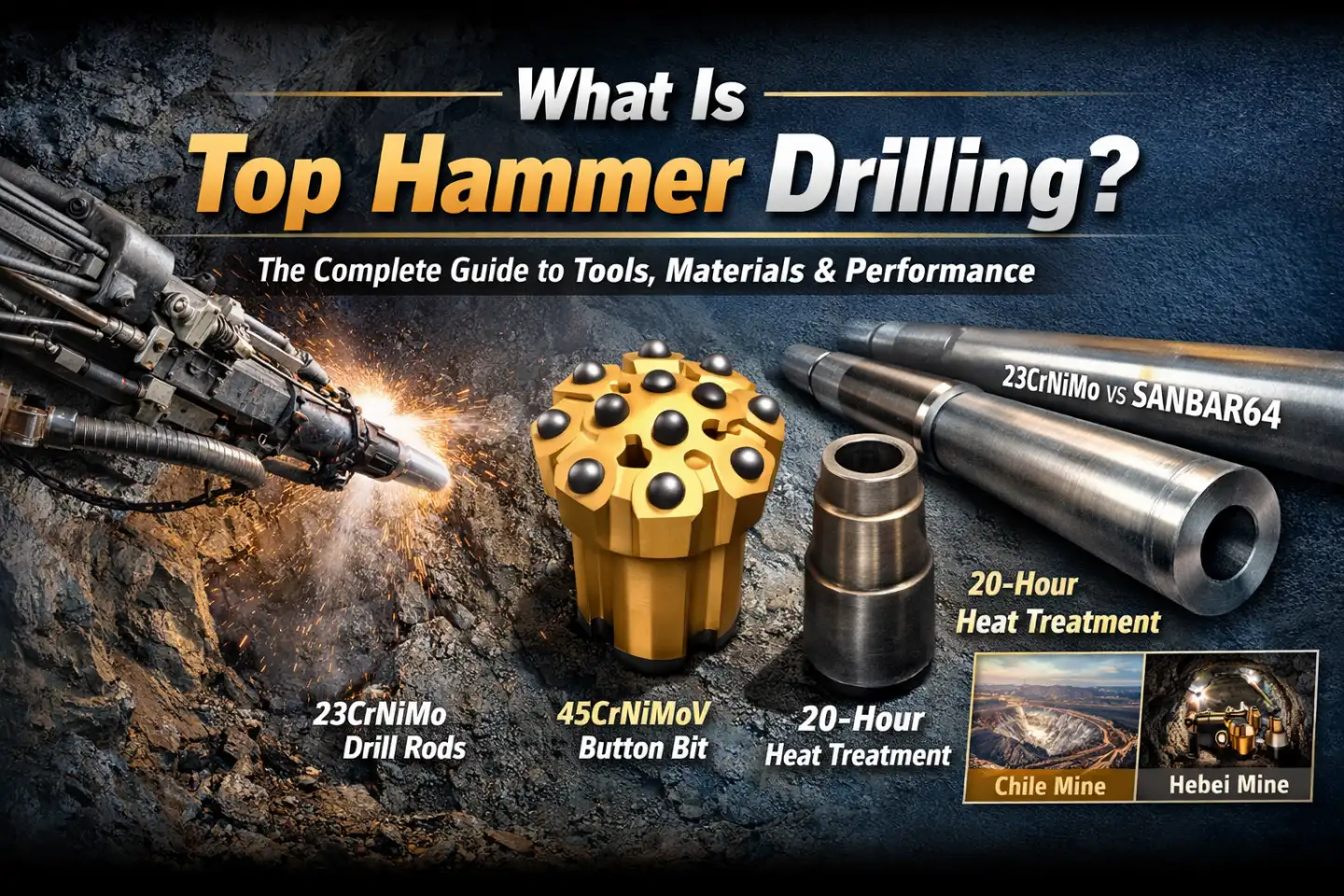
Among the major percussive drilling methods, Top Hammer Drilling consistently delivers the highest penetration rates and lowest cost-per-meter (CPM) in medium to hard rock formations — when the right tools are selected, correctly specified, and properly maintained.
But what exactly is top hammer drilling? And what separates a drill string that survives 50 meters from one that exceeds 300?
At RockHound, we engineer and manufacture the complete top hammer drill string — from shank adapters to button bits. This guide explains the mechanics, the material science, the engineering design principles, and the real-world performance data behind high-performance top hammer systems.
What Is Top Hammer Drilling? Mechanism & Principle
Top hammer drilling is a percussive rotary drilling method in which the impact energy is generated entirely above ground — at the top of the drill string — by a hydraulic or pneumatic rock drill (drifter). This distinguishes it from DTH (Down-The-Hole) drilling, where the hammer travels down the hole and strikes the bit directly at the rock face.
In a top hammer system, the drifter delivers high-frequency axial blows — typically at 2,000–4,500 beats per minute (bpm) — combined with continuous rotation (torque) and thrust. This percussive energy travels sequentially through the drill string:
Drifter Piston → Shank Adapter → Drill Rods (+ Coupling Sleeves) → Button Bit → Rock Face
The bit’s carbide buttons crush and fracture the rock through a combination of dynamic impact and rotary shearing, while the flushing medium (water or compressed air) evacuates cuttings from the hole.
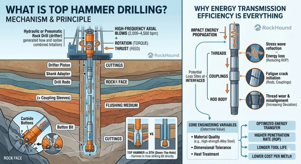
Why Energy Transmission Efficiency Is Everything
Unlike DTH systems — where the hammer is always in direct contact with the bit — top hammer drilling depends on efficient stress wave propagation through multiple threaded connections along the drill string. Every interface (thread, coupling, rod body) represents a potential site for:
- Stress wave reflection and energy loss — reducing the effective energy delivered to the bit face
Fatigue crack initiation — in rods and couplings subjected to repeated tensile-compressive cycles
Thread wear and misalignment — which further degrades energy transmission and increases deviation
This is precisely why material quality, dimensional tolerance, and heat treatment are not optional premium features — they are the core engineering variables that determine whether a drill string delivers value or cost.
Core Components of the Top Hammer Drill String
A complete top hammer system is a mechanically interdependent chain. Optimizing one component while neglecting another creates performance bottlenecks. Here is a breakdown of each element.
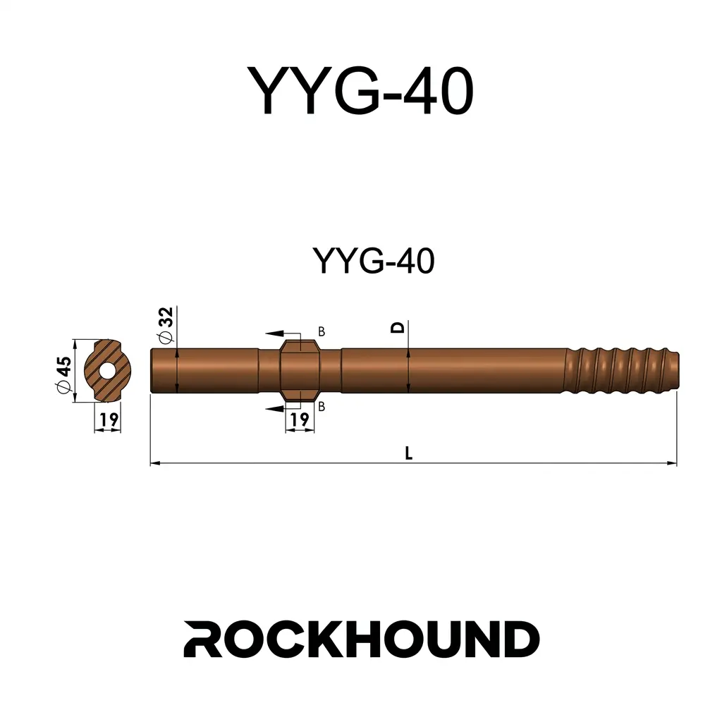
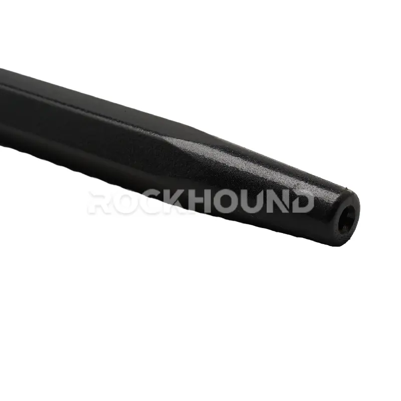
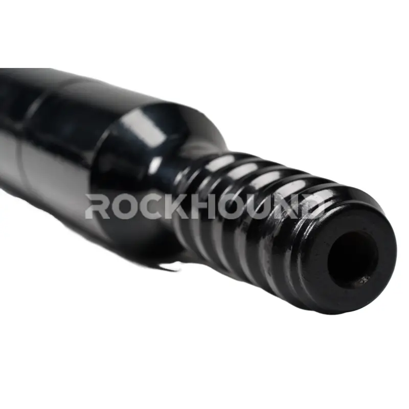
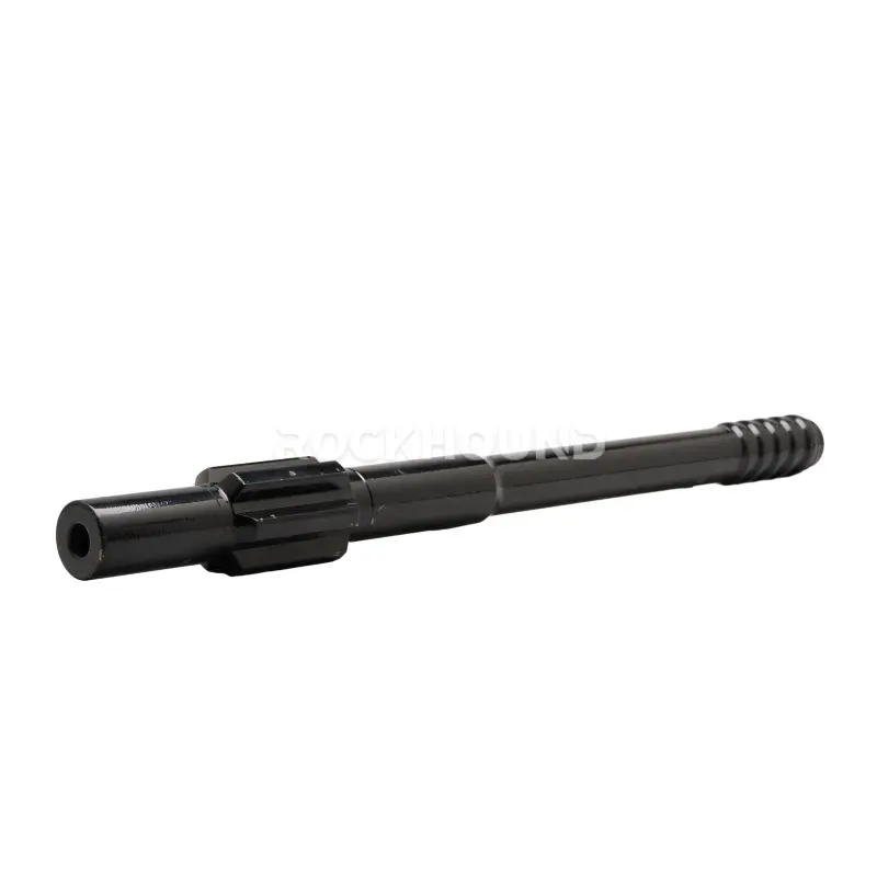
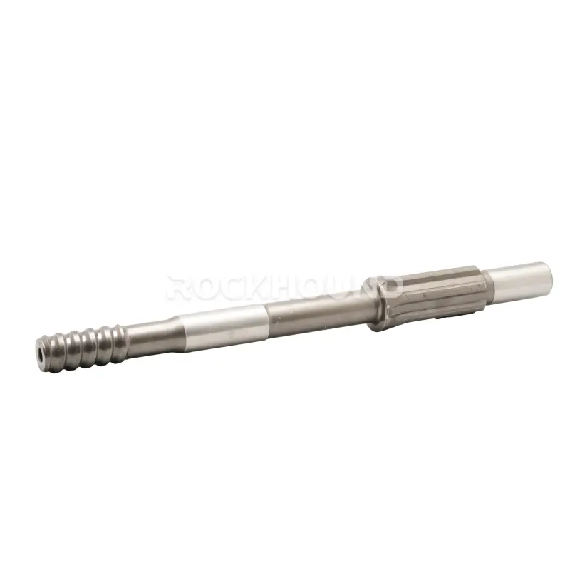
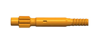
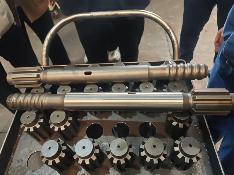
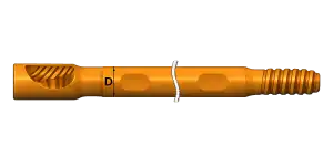
Shank Adapter
The shank adapter is the first energy transfer point in the drill string — the direct interface between the drifter piston and the drill rods. It receives the highest-intensity impact loads in the entire system and must simultaneously transmit axial stress waves, resist torsional shear from drill rotation, and survive millions of high-energy blows without thread fatigue or shank deformation.
Shank adapters must be matched precisely to the drifter model (e.g., Atlas Copco, Sandvik, Furukawa) in terms of shank geometry, thread standard, and impact energy rating.
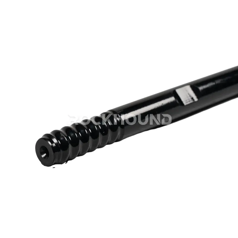
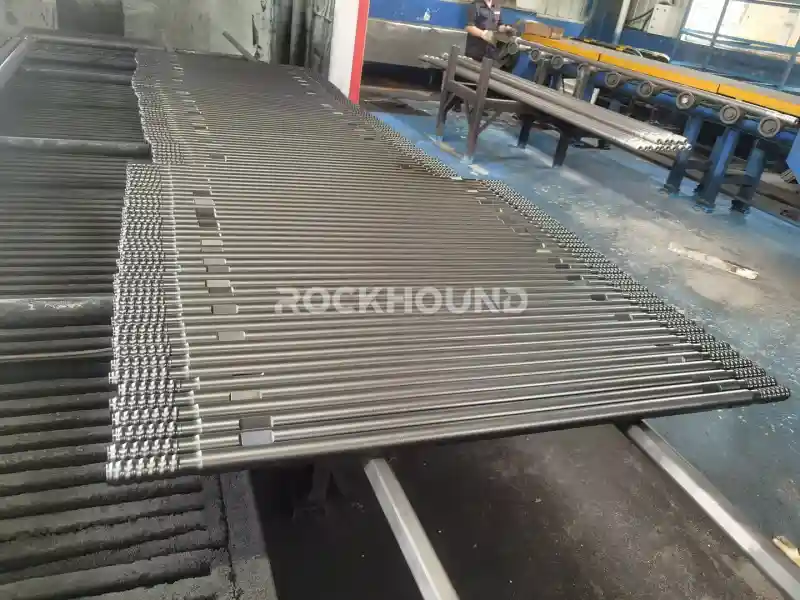
Drill Rods
Drill rods form the structural backbone and energy conduit of the drill string. They transmit percussive stress waves from the shank adapter to the bit while simultaneously conveying rotation torque and allowing flushing fluid to pass through the center bore.
Top hammer drill rods come in two principal configurations:
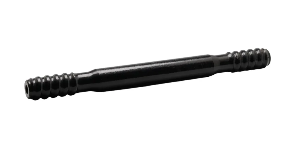
Extension Drill Rods feature a female thread on both ends and require a separate coupling sleeve to join lengths together. They are the standard choice for deeper holes requiring staged rod addition.
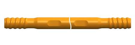
Speed MF (Male-Female) Rods incorporate integral male and female threads on opposing ends, eliminating the need for a separate coupling sleeve. This reduces component count, simplifies rod changing, and improves thread alignment accuracy — resulting in better hole straightness and faster operations.
→ Rock Drill Rods: Types, Work, Choose & Maintenance → What Is an Extension Drill Rod? Types, Materials & Selection Guide → Speed MF Rod vs Extension Drill Rod: Difference & How to Choose
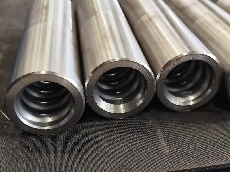
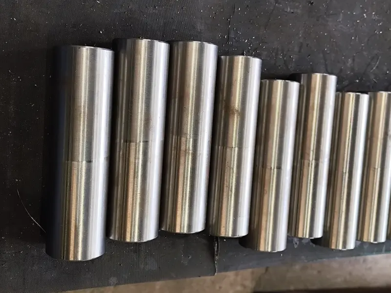
Coupling Sleeves
When extension rods are used, coupling sleeves serve as the mechanical joints connecting individual rod lengths. They are a critical but often overlooked link in the energy chain: a coupling sleeve with poor thread accuracy, insufficient wall thickness, or inadequate heat treatment will develop fretting wear, reduce energy transmission efficiency, and fail prematurely — introducing rod-drop risk and collateral damage to the drill string.
Coupling sleeves must be specified to match the thread standard (R22, R25, R28, R32, R38, T38, T45, T51, etc.) and the operating impact energy of the drifter.
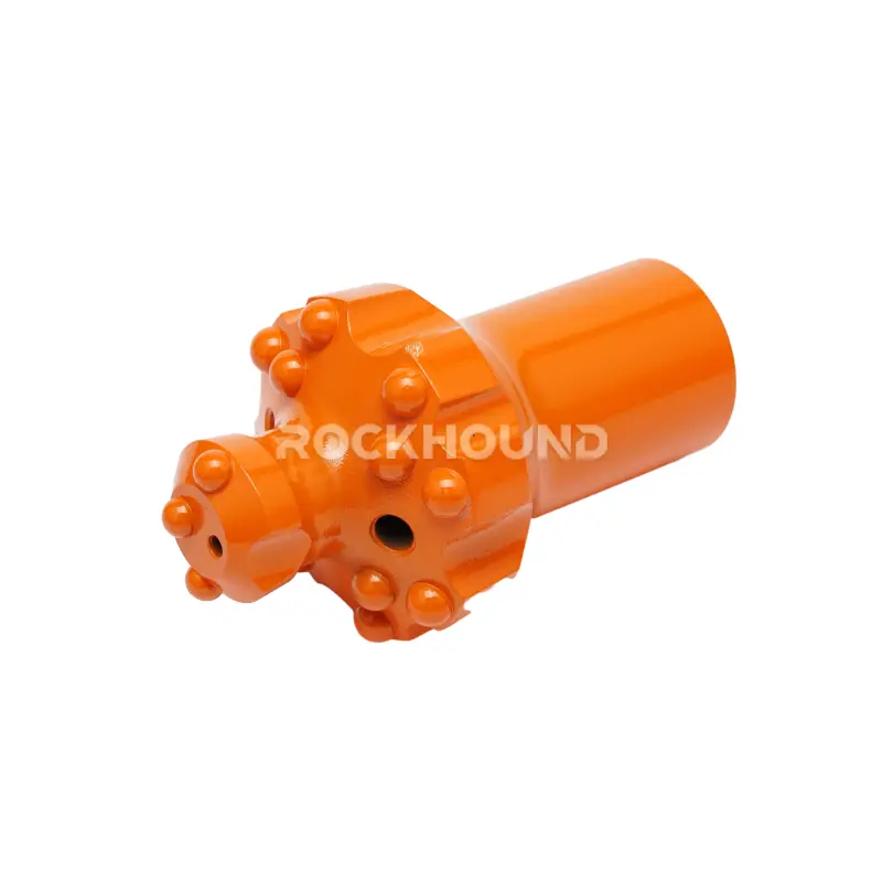
Top Hammer Button Bits
The button bit is the terminal energy conversion component — where all the kinetic energy accumulated through the drill string is finally delivered as crushing force against the rock. Its carbide buttons penetrate and fracture the rock face with each impact, while the bit body geometry governs hole diameter, flushing efficiency, and directional stability.
Top hammer button bits are available in multiple face configurations and button shapes, each engineered for specific rock types and drilling conditions.
Material Science: The Foundation of Tool Longevity
In top hammer drilling, material selection and metallurgical processing determine the majority of tool service life — far more than geometry alone. At RockHound, the alloy specifications for drill bit bodies and drill rods are deliberately differentiated because each component faces a distinct dominant stress regime.
Drill Bit Body Material: 45CrNiMoV vs. Standard Industry Grades
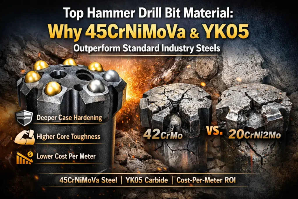
RockHound button bit bodies are manufactured from 45CrNiMoV high-alloy steel — a medium-carbon, multi-element alloy combining Chromium (Cr), Nickel (Ni), Molybdenum (Mo), and Vanadium (V). The role of each alloying element is precisely defined:
| Alloying Element | Function in Button Bit Performance |
|---|---|
| Chromium (Cr) | Forms stable carbides during case carburizing; increases surface hardenability and wear resistance against abrasive rock |
| Nickel (Ni) | Enhances core toughness and low-temperature fracture resistance; suppresses brittle fracture at the bit shank and button seats under high-energy impact |
| Molybdenum (Mo) | Refines prior austenite grain size; prevents temper embrittlement; improves fatigue strength at threaded and shank zones |
| Vanadium (V) | Forms fine vanadium carbide precipitates; pins grain boundaries during carburizing; maintains dimensional stability and fine microstructure integrity |
This specification positions 45CrNiMoV measurably above common alternatives like 42CrMo (which lacks Ni and V), 20CrNi2Mo (optimized for rods, not bits), or 35CrMo (insufficient fatigue resistance for high-frequency impact loads) — all of which show earlier case spalling, higher button ejection rates, and reduced thread life under equivalent mining conditions.
→ Top Hammer Drill Bit Material: 45CrNiMoV & YK05 Performance
Tungsten Carbide Button Grade: YK05
The cutting performance and wear life of a button bit ultimately depends on its carbide button specification. RockHound uses YK05 premium-grade tungsten carbide — a fine-grain WC-Co composite engineered specifically for high-impact percussive drilling in abrasive rock.
The YK05 grade is selected for its combination of:
- High transverse rupture strength (TRS) — resisting button fracture under peak impact loads
- Elevated hardness — sustaining gauge diameter and button shape retention over extended meterage in abrasive formations (CAI > 4.0)
- Fatigue crack resistance — preventing progressive subsurface micro-cracking at the button-body interface
In hard, abrasive rock formations with UCS values exceeding 180 MPa — such as the granodiorite formations encountered in RockHound’s Chile copper mine field test — YK05 carbide buttons maintain their geometry and contact area far longer than standard WC-Co grades, directly translating into slower ROP decline and higher meters-per-regrind.
Drill Rod Material: 23CrNiMo vs. Sanbar64
For drill rods and coupling sleeves, the dominant failure mode shifts from surface wear and button-seat fatigue to bending fatigue, torsional stress fracture, and thread fatigue at connection zones. This requires a different alloy philosophy: lower carbon content for superior core toughness and fatigue ductility, with sufficient hardenability for effective case carburizing.
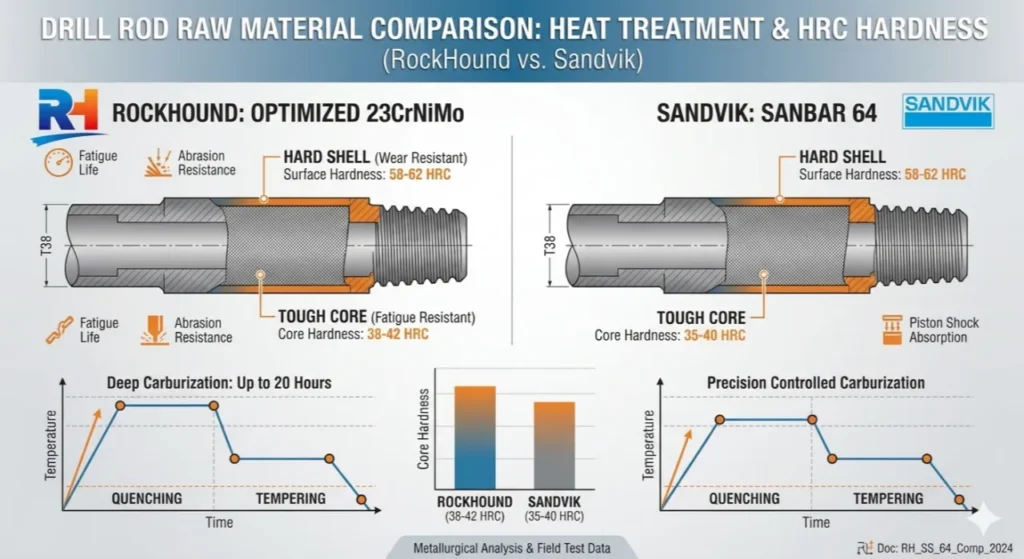
RockHound drill rods are manufactured from 23CrNiMo alloy steel, which offers:
- Superior fatigue resistance under the cyclic tensile-compressive loading of high-frequency impact
- Consistent response to the 20-hour case carburizing process, developing a hardened surface layer while maintaining a ductile, tough core
- Higher impact toughness at the threaded end zones — the primary site of rod-end fracture
In comparative analysis against Sanbar64 (a boron-modified steel commonly used for drill rod applications), 23CrNiMo demonstrates better low-cycle fatigue performance and more predictable heat treatment response under the thermal cycling conditions of demanding mining operations — making it the specification of choice for heavy-duty and high-frequency drifter applications.
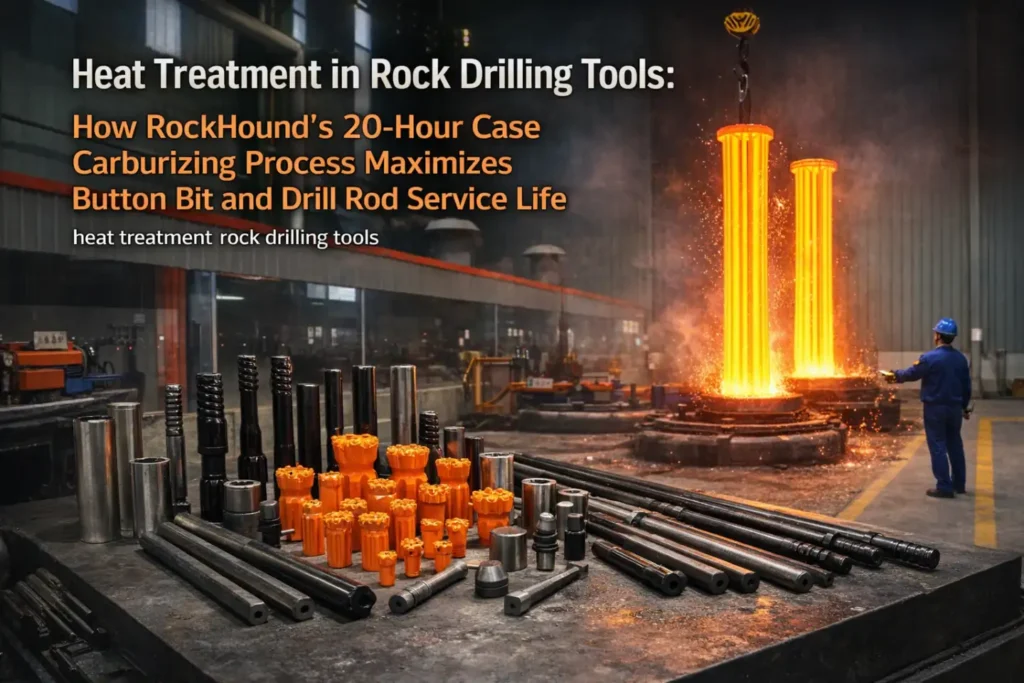
The 20-Hour Heat Treatment Advantage
Material selection sets the potential — heat treatment determines whether that potential is realized. At RockHound, heat treatment is not a single finishing step: it is a precisely controlled thermochemical manufacturing sequence that lasts a minimum of 20 hours for button bits and coupled rods alike.
The Core Challenge: Contradictory Properties
Unprocessed steel cannot simultaneously be hard (wear-resistant) and tough (impact-absorbing). These properties are fundamentally contradictory in a homogeneous material. The solution is to engineer a gradient structure:
- Hard, carbon-enriched outer case → resists abrasive wear, contact fatigue, and surface deformation
- Tough, ductile core → absorbs cyclic impact energy without brittle fracture propagation
This is achieved through the case carburizing cycle.
The RockHound 20-Hour Carburizing Protocol
The process comprises three sequentially controlled stages, each critical to the final microstructure:
Stage 1 — Controlled Atmosphere Carburizing (the “20-hour” phase) Components are held at elevated temperature (typically 880–940°C) inside a sealed furnace with a carbon-rich atmosphere (endothermic gas + hydrocarbon enrichment). Carbon diffuses inward from the surface, building a case depth of 1.2–2.0 mm depending on component cross-section and target application. The extended 20-hour duration — longer than the 8–12 hour cycles used in commodity production — achieves:
- Deeper effective case depth for improved fatigue crack initiation resistance
- More uniform carbon concentration profile, reducing case-core transition brittleness
- Complete carburization of complex geometries including thread roots and flushing channel edges
Stage 2 — Direct Quenching Immediately following carburizing, components are quenched in oil or polymer media. This rapid cooling transforms the austenitic case into martensite — the hard, wear-resistant phase — while the lower-carbon core transforms into lower-bainite or tempered martensite, preserving toughness.
Stage 3 — Low-Temperature Tempering A final tempering cycle at 150–200°C relieves quench-induced residual stresses and reduces the risk of delayed cracking, while minimally reducing case hardness. This step is essential for long-term dimensional stability and fatigue performance.
Practical Performance Outcomes
| Performance Parameter | Properly Heat-Treated (20hr) | Commodity (Short Cycle) |
|---|---|---|
| Surface hardness (HRC) | 58–62 | 52–56 |
| Effective case depth | 1.2–2.0 mm | 0.6–1.0 mm |
| Thread fatigue life | High — resists initiation at root | Lower — early cracking at thread roots |
| Button seat retention | Excellent | Moderate — button ejection risk |
| Core impact toughness | Preserved (ductile core) | Often compromised (through-hardened zones) |
The direct operational outcome: fewer rod breaks, lower bit replacement frequency, and a meaningfully lower cost-per-drilled-meter — the metric that matters most to drilling contractors and mine operators.
→ 20-Hour Heat Treatment in Rock Drilling Tools — Full Technical Guide
Engineering Design: Matching Bit & Rod to Rock Conditions
Even the best materials and heat treatment cannot compensate for a mismatched tool design. Correct engineering selection can improve drilling efficiency by 15–25% and reduce bit consumption by a comparable margin.
Bit Face Design Selection
The face geometry of a button bit governs how the carbide buttons contact the rock, how cuttings are evacuated from the hole, and how well hole straightness is maintained.
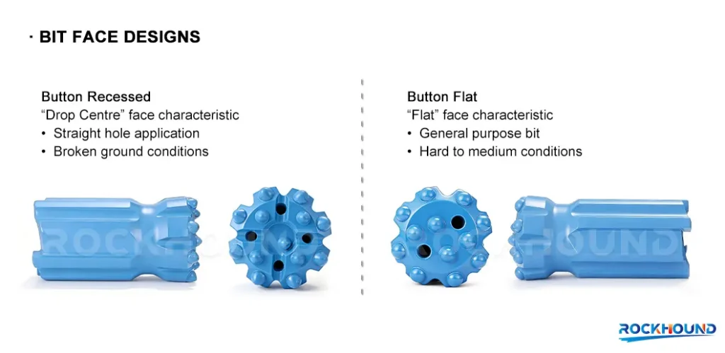
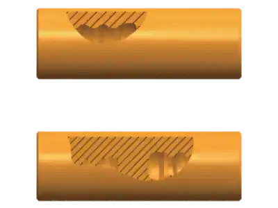
Flat Face
The buttons are arranged on a planar face. This geometry concentrates maximum energy directly forward, making it ideal for hard, massive, homogeneous rock (granite, basalt, quartzite) where rock breakage is the primary challenge and hole deviation is less of a concern.
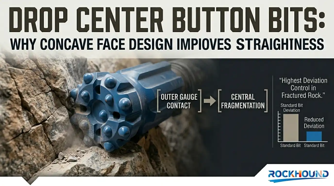
Drop Center (Concave)
The center of the bit face is recessed below the gauge buttons. This geometry improves flushing channel access to the center of the hole, reducing cuttings re-grinding — particularly effective in fractured or jointed rock where cuttings tend to pack in the center zone.
Convex (Dome)
A convex face profile provides inherently better hole straightness and guidance stability — preferred when drilling in variable or laminated formations where lateral bit deflection is a risk.
Retrac Skirt
The retrac design incorporates back-reaming buttons on the bit skirt, allowing the bit to ream back through the hole when the drill string is withdrawn. This feature is critical in fractured, broken, or collapsing rock where rod jamming is a frequent operational hazard.
Button Shape Selection
Spherical Buttons The classical button geometry. Spherical buttons offer the highest button body volume and therefore the best durability under repeated high-energy impacts — particularly in hard, abrasive rock where button fracture is the primary failure mode. They are the standard choice for maximum service life.
Ballistic (Semi-Ballistic) Buttons A more pointed profile that concentrates the impact force onto a smaller contact area, generating higher local compressive stress on the rock. This results in faster penetration rates (ROP) in medium-hard rock, though at the cost of slightly reduced button durability under extreme abrasion.
The practical selection rule: in formations where abrasivity (CAI) exceeds 3.5, spherical buttons extend grinding intervals and reduce total tool consumption; in medium-hardness formations, ballistic buttons pay back in faster cycle times and lower drilling cost-per-meter through speed.
Rod Configuration Selection
The choice between Extension Rods and Speed MF Rods should be driven by:
| Factor | Extension Rods | Speed MF Rods |
|---|---|---|
| Hole depth | Very deep holes requiring many rod lengths | Short to medium depths |
| Change speed | Slower (separate coupling required) | Faster (integral thread, no coupling) |
| Hole straightness | Depends on coupling quality | Inherently better alignment |
| Maintenance | Couplings wear independently, easy to replace | Slightly higher per-rod cost, but fewer parts |
| Optimal application | Long-hole stoping, production drilling | Development, tunneling, fast-cycle production |
Field-Proven Performance: Real Mine Data
Laboratory tests validate material properties. Field performance data validates engineering decisions in the conditions that actually matter — under production pressures, real rock, and realistic maintenance regimes.
Test 1: MF T38-R32 Drill Rods & Bits — Iron Mine, Hebei Province, China
Site conditions: High-iron magnetite formation, high quartz content, frequent abrasive wear on gauge and flushing channels. High drifter impact frequency (T38 class) with minimal rod change downtime requirements.
Outcome summary:
- RockHound MF T38-R32 rods demonstrated consistent performance across multiple drill shifts without thread fatigue or mid-body fracture
- Button bit gauge retention was maintained through significantly more meters than previously used alternative-brand tools
- Cost-per-meter was reduced vs. incumbent Tier-1 brand tools — achieved through longer tool life rather than lower upfront price
- Rod failure rate (mid-body fracture + thread stripping) remained at near-zero through the test period
→ Full Field Test Report: MF T38-R32 Drill Rods & Bits at Iron Mine
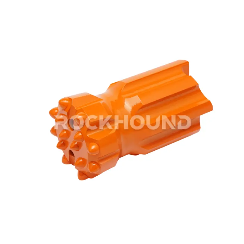
Test 2: R32 51mm Retrac Button Bit — Copper Mine, Chile
Site conditions: Among the most demanding encountered in RockHound’s field validation program. Granodiorite and intrusive igneous rock with:
- UCS commonly exceeding 180 MPa
- CERCHAR Abrasivity Index (CAI) > 4.0 (extreme abrasion category)
- Rock Quality Designation (RQD) ranging from 50–90%
These parameters represent conditions that rapidly destroy under-specified tooling — particularly through button fracture, gauge loss, and body fatigue.
Performance result:
- RockHound R32 51mm Retrac bit achieved a service life exceeding 310 meters before requiring replacement — well above the baseline performance of standard-grade bits in equivalent Chilean mining applications
- Button shape retention (spherical YK05 carbide) remained excellent through 250+ meters, with minimal gauge wear observed
- No body fracture or button ejection incidents were recorded throughout the test
Why it matters for procurement: A bit that achieves 310 meters under CAI > 4.0 conditions at a comparable or lower price point than competitors achieving 150–200 meters in the same formation directly halves the number of bit changes, the associated drill downtime, and the consumables budget line.
→ R32 51mm Retrac Button Bit for Hard Rock — Chile Copper Mine Report
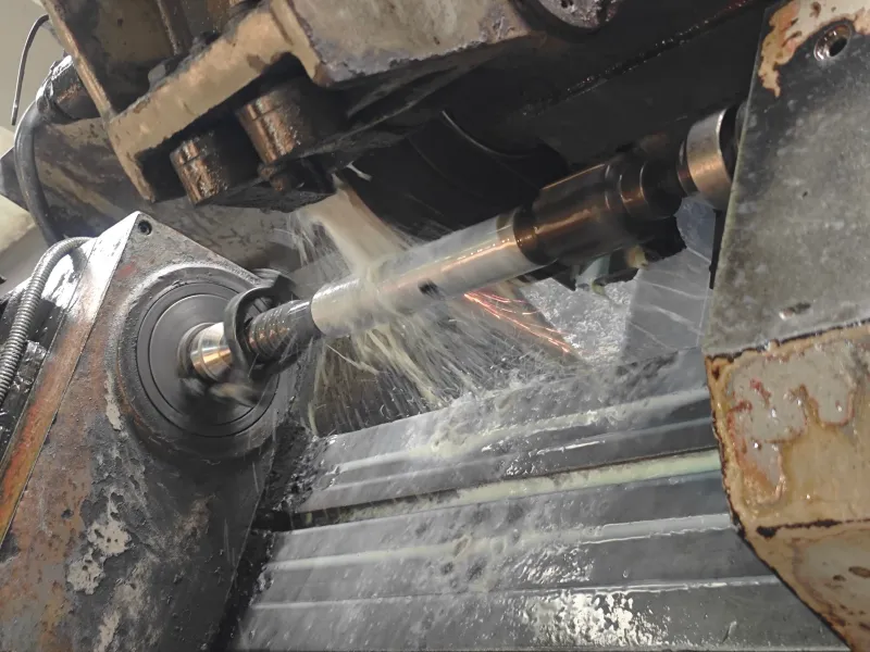
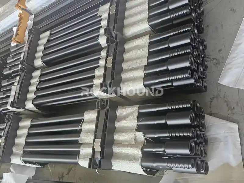
Manufacturing Process: From Raw Steel to Finished Drill String
Consistent field performance requires consistent manufacturing. At RockHound, every component in the drill string follows a documented, controlled production process. Transparency in manufacturing is a prerequisite for trust in technical specification.
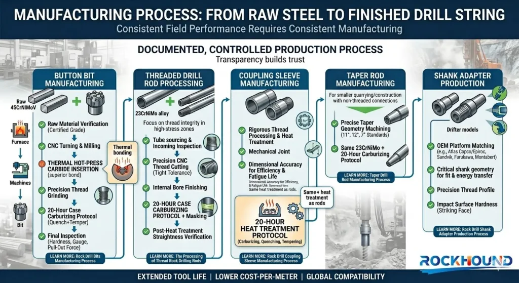
Button Bit Manufacturing
The production sequence for RockHound button bits includes:
- Raw material verification (45CrNiMoV bar stock, certified grade)
- CNC turning and milling of bit body geometry and flushing channel profiles
- Thermal (hot-press) carbide button insertion — interference fitting via controlled thermal expansion for a mechanically superior bond vs. cold-press methods
- Thread grinding to precision tolerance
- 20-hour controlled atmosphere case carburizing + quench + temper
- Final inspection: case hardness, thread gauge check, button pull-out force test
Threaded Drill Rod Processing
Rod manufacturing is centered on thread integrity — the highest-stress zone and the most common failure initiation site in a drill string.
Key processing stages:
- 23CrNiMo alloy steel tube sourcing and incoming inspection
- Precision CNC thread cutting — pitch, profile, and concentricity within tight tolerance
- Internal bore finishing for flushing fluid flow consistency
- Case carburizing (20-hour protocol) with thread zone masking controls
- Straightness verification post heat treatment
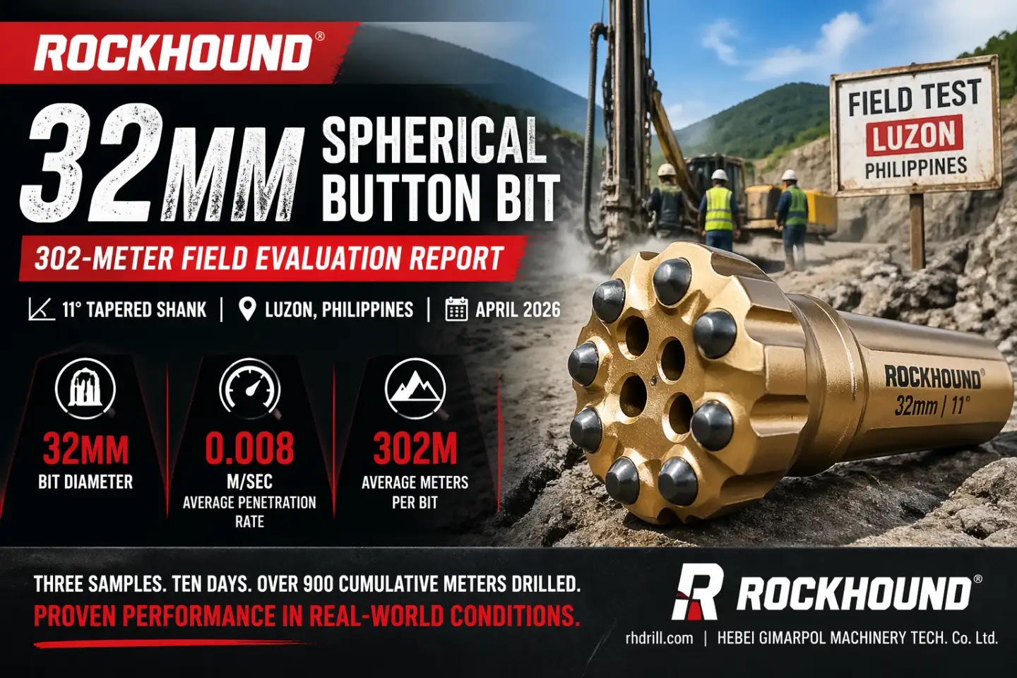
Taper Rod Manufacturing
For smaller-scale quarrying, construction, and secondary breaking applications using tapered (non-threaded) rod-bit connections:
- Taper geometry is machined to precise tolerance (11°, 12°, 7° taper standards)
- Steel selection and heat treatment follow the same 23CrNiMo + 20-hour carburizing protocol
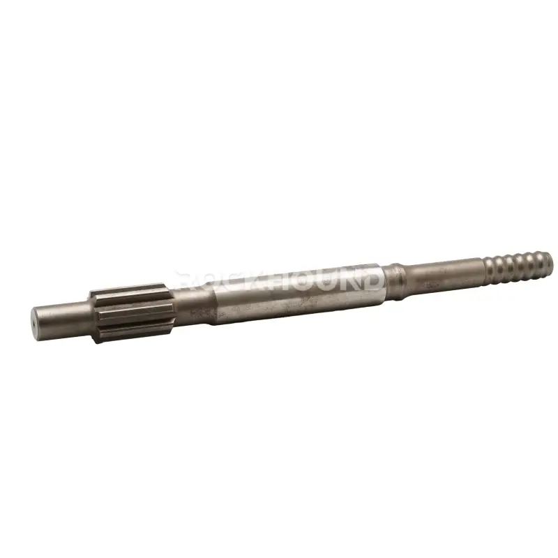
Shank Adapter Production
Shank adapters are produced to match specific drifter models across the major OEM platforms (Atlas Copco/Epiroc, Sandvik, Furukawa, Montabert, etc.), with particular attention to:
- Shank geometry dimensional accuracy (critical for drifter fit and energy transfer)
- Thread profile precision for drill rod connection
- Impact surface hardness at the striking face
Coupling Sleeve Manufacturing
Coupling sleeves undergo the same thread processing and heat treatment rigor as rods — as the mechanical joint in the drill string, their dimensional accuracy directly affects energy transmission efficiency and threaded connection fatigue life.
How to Evaluate Total Drilling Economics
The most common procurement mistake in rock drilling consumables is optimizing for unit price rather than cost-per-meter. Consider:
A button bit priced 30% lower than a RockHound equivalent that achieves half the service life costs 40% more per drilled meter — before accounting for the additional downtime, rod change labor, and rod wear caused by more frequent bit replacements.
The correct evaluation framework:
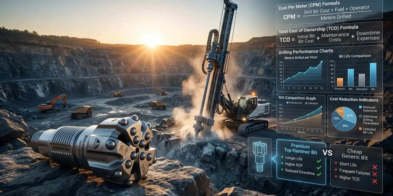
Cost Per Meter (CPM) = (Tool Unit Cost + Rod Wear Cost + Downtime Cost) ÷ Total Meters Drilled
RockHound tools are engineered to minimize CPM — not unit price. The levers are:
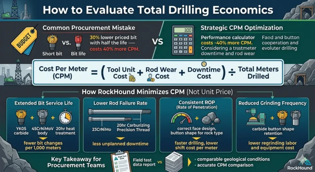
Extended bit service life
(YK05 carbide + 45CrNiMoV body + 20hr heat treatment) → fewer bit changes per 1,000 meters
Lower rod failure rate
(23CrNiMo + 20hr carburizing + precision thread) → less unplanned downtime
Consistent ROP
(correct face design + button shape for rock type) → faster drilling, lower shift cost per meter
Reduced grinding frequency
(carbide button shape retention) → lower regrinding labor and equipment cost
For drilling contractors and mine procurement teams evaluating top hammer tooling suppliers, requesting field test data under comparable geological conditions — rather than relying on catalog specifications — is the most reliable path to an accurate CPM comparison.
Conclusion
Top hammer drilling is not simply a category of rock drill — it is a precisely engineered system where every component’s performance depends on the quality of every other component, and where the difference between a profitable operation and an underperforming one is often determined at the metallurgical level.
To extract maximum performance from a top hammer system, operators must optimize across:
- Material specification (45CrNiMoV for bits, 23CrNiMo for rods — not interchangeable)
- Heat treatment integrity (20-hour carburizing, not a shortcut 8-hour cycle)
- Component design matching (face geometry, button shape, rod configuration for the specific rock type)
- Manufacturing dimensional accuracy (thread precision, case depth uniformity, carbide insertion quality)
- Field-validated performance data (real CPM under real geological conditions)
At RockHound, we manufacture and supply the complete top hammer drill string — engineered to these standards, validated in the field, and specified to your geological conditions.
Ready to Reduce Your Cost Per Meter?
Explore RockHound’s full range of Top Hammer Rock Drilling Tools, or contact our engineering team to discuss:
- Site-specific tool selection and specification
- Customized field testing programs
- Technical support for drifter-to-bit drill string optimization
FAQ
Top hammer drilling is a percussive rotary drilling method in which a hydraulic or pneumatic rock drill (drifter) generates high-frequency impact energy above ground — at the "top" of the drill string — and transmits it downward through the shank adapter, drill rods, coupling sleeves, and finally to the button bit at the rock face.
The drifter delivers between 2,000 and 4,500 blows per minute combined with continuous rotation and thrust. The button bit's tungsten carbide inserts crush and fracture the rock on impact, while compressed air or water flushes cuttings from the hole.
This method is distinct from DTH (Down-The-Hole) drilling, where the hammer travels inside the hole and strikes the bit directly — in a top hammer system, the entire percussive force must travel through the full length of the drill string, which is why material quality and thread precision are so critical to performance.
The fundamental difference is the location of the hammer. In top hammer drilling, the hammer (drifter) sits at the surface and transmits impact energy through a series of threaded rods to the bit.
In DTH drilling, the hammer is positioned at the bottom of the hole, directly behind the bit, so impact energy is delivered without traveling through rod connections. DTH systems are generally favored for deep, straight holes in very hard rock where energy loss over long rod strings would significantly reduce top hammer efficiency.
Top hammer drilling offers higher penetration rates, lower equipment cost, and superior cost-per-meter performance for shallow to medium-depth holes in medium to hard rock — typically up to 50–60 meters depending on formation. For mining development, quarrying, and construction applications in this depth range, top hammer remains the most productive and economical choice.
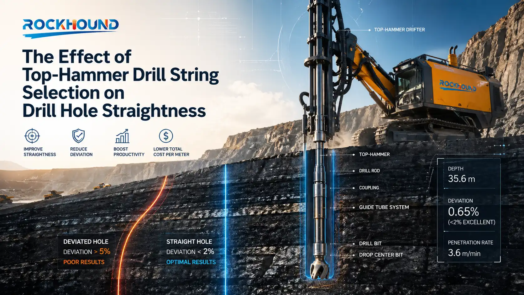
A complete top hammer drill string consists of four interdependent components.
- The shank adapter is the first link in the chain, connecting the drifter piston directly to the drill string and receiving the highest-intensity impact loads in the system.
- Drill rods form the structural backbone and energy conduit, transmitting percussive stress waves and rotation torque while conveying flushing fluid through the center bore.
- Coupling sleeves join individual rod lengths when extension rods are used, and must maintain thread integrity and dimensional accuracy to minimize energy loss at each connection point.
- The button bit is the terminal component where accumulated energy is delivered to the rock face through tungsten carbide buttons that crush and fracture the formation.
Each component must be correctly specified and matched to the others — a weak link at any point reduces the performance of the entire system.
High-performance top hammer button bits consist of two distinct material systems working in combination.
- The bit body is manufactured from 45CrNiMoV high-alloy steel — a medium-carbon, multi-element alloy containing Chromium, Nickel, Molybdenum, and Vanadium. Each element serves a specific metallurgical function: Chromium increases surface hardenability and wear resistance, Nickel enhances core toughness and fracture resistance under high-energy impact, Molybdenum refines grain size and improves fatigue strength at threaded zones, and Vanadium forms fine carbide precipitates that maintain microstructural integrity during the carburizing process.
- The cutting inserts are manufactured from YK05 premium-grade tungsten carbide — a fine-grain WC-Co composite selected for its combination of high transverse rupture strength, elevated hardness, and fatigue crack resistance in abrasive rock with CERCHAR Abrasivity Index values above 4.0. This material pairing is what separates professional-grade tooling from commodity products in hard and abrasive mining conditions.
Heat treatment is the manufacturing process that determines whether a drilling tool's material potential is actually realized in the field. The core challenge is that unprocessed steel cannot simultaneously be hard (wear-resistant) and tough (impact-absorbing) — these properties are fundamentally contradictory in a homogeneous material.
Case carburizing heat treatment solves this by engineering a gradient structure: a hard, carbon-enriched outer case that resists abrasive wear and contact fatigue, over a tough, ductile core that absorbs cyclic impact energy without brittle fracture.
A properly executed 20-hour carburizing cycle achieves a case depth of 1.2–2.0 mm with surface hardness in the 58–62 HRC range, compared to the 0.6–1.0 mm case and 52–56 HRC typical of commodity short-cycle heat treatment.
The practical consequence of this difference shows up as extended thread life, reduced button ejection incidents, and significantly lower cost-per-drilled-meter across a production shift.
Both 23CrNiMo and Sanbar64 are alloy steels used in the manufacture of top hammer drill rods and coupling sleeves. The key distinction lies in their fatigue performance characteristics under the specific stress regime that drill rods experience: high-frequency cyclic tensile-compressive loading at 2,000–4,500 bpm, combined with torsional shear at threaded connections and bending fatigue along the rod body.
- 23CrNiMo — a low-carbon Chromium-Nickel-Molybdenum alloy steel — offers superior low-cycle fatigue resistance, higher impact toughness at thread end zones, and more consistent response to case carburizing heat treatment, resulting in a more predictable and uniform hardened surface layer over the rod body.
- Sanbar64 is a boron-modified steel that performs adequately in less demanding drifter applications but shows comparatively earlier fatigue crack initiation at thread roots under heavy-duty, high-frequency impact conditions.
For demanding mining environments with large-format drifters and high operational tempos, 23CrNiMo is the more reliable specification for both service life and failure rate predictability.
Bit face design selection should be driven primarily by rock hardness, structure, and the relative priority of penetration rate versus hole straightness.
- A flat face design places all buttons on a planar surface, concentrating maximum forward energy — the correct choice for hard, massive, homogeneous rock such as granite, basalt, or quartzite where energy delivery is the primary requirement.
- A drop center (concave) face recesses the central zone below the gauge buttons, which improves flushing channel access and reduces cuttings re-grinding in fractured or jointed rock.
- A convex face provides inherently better directional stability and guidance, suited to variable or laminated formations where lateral deflection is a risk.
- A retrac skirt incorporates back-reaming buttons that allow the bit to ream back through the hole during rod withdrawal — essential in broken, collapsing, or heavily fractured rock where rod jamming presents a serious operational hazard. In terms of button shape, spherical buttons offer maximum durability in highly abrasive rock above CAI 3.5, while ballistic (semi-ballistic) buttons deliver faster penetration rates in medium-hardness formations at the cost of marginally shorter service life.
Service life varies considerably depending on rock type, drifter energy class, flushing efficiency, bit specification, and regrinding practice.
- In extremely hard and abrasive conditions — such as granodiorite formations in Chile with UCS values exceeding 180 MPa and CERCHAR Abrasivity Index above 4.0 — a properly specified bit using 45CrNiMoV steel bodies and YK05 carbide buttons, processed through a full 20-hour heat treatment cycle, can achieve service lives exceeding 310 meters before replacement.
- In less abrasive iron ore formations such as magnetite-bearing rock in Hebei Province, China, service life is typically higher and grinding intervals are extended further. The critical point for procurement is that raw meterage per bit is less meaningful than cost-per-meter: a bit achieving 310 meters at a given price point delivers a fundamentally different economic outcome than one achieving 150 meters at a 20% lower unit cost.
Evaluating tooling suppliers on field-test CPM data under comparable geological conditions — rather than on catalog price — is the most reliable basis for procurement decisions.
Speed MF (Male-Female) rods incorporate integral male and female threads on opposing ends, eliminating the need for a separate coupling sleeve at each rod joint.
Extension rods require a separate coupling sleeve to connect rod lengths. The practical case for Speed MF rods is strongest in applications where rod-change cycle time is a significant productivity constraint — development headings, tunneling, and high-cycle production drilling — because the reduced component count and integral thread alignment improve both change speed and hole straightness.
Extension rods with separate couplings remain the better choice for very deep holes requiring many rod lengths, where the ability to replace worn couplings independently (rather than replacing the entire rod) offers a cost advantage, and where downhole conditions demand maximum flexibility in rod string configuration.
Regardless of system choice, thread precision and heat treatment quality remain the governing factors in energy transmission efficiency and fatigue life at the rod connection zones.
Cost-per-meter is the total consumable and downtime cost divided by the total meters drilled in a given period, and it is the only metric that accurately captures the true economic performance of a drilling tool selection.
A drill bit with a lower purchase price that achieves half the service life of a premium alternative does not save money — it costs more per meter drilled, and introduces additional downtime costs from more frequent bit changes and the associated rod wear from operating a degraded bit.
The full CPM formula must account for tool unit cost, rod wear attributable to that tool, labor cost of bit changes, and unplanned downtime from premature failures. In high-production mining operations, even a modest reduction in CPM — achieved through longer bit life, fewer rod breaks, or a higher sustained penetration rate — compounds into substantial savings across a fleet of drills over a full operating year.
This is why the most rigorous buyers in the mining industry request field test reports with CPM data under defined geological conditions rather than relying on manufacturer specifications alone.